Hotrodtractor
Moderator
Why not remove the column shifter all together and shift the valve body using a servo much like what many of the over the road automatic trucks use - specifically like the Allison 1000 in the box van trucks?

Why not remove the column shifter all together and shift the valve body using a servo much like what many of the over the road automatic trucks use - specifically like the Allison 1000 in the box van trucks?
Why not remove the column shifter all together and shift the valve body using a servo much like what many of the over the road automatic trucks use - specifically like the Allison 1000 in the box van trucks?
It took me 3 trial orders to get these.Do you have some pics and or part number for the 110v outlets? I have not located any that I like yet. Thanks.
Some time ago I worked on a transmission and control system for a Baja racing team. We were using the 4R100 trans, which was the newest trans at the time.The plan is to have a 2 positon electronic shifter (forward = up, back = down) built into the console with buttons on the shift knob for various other functions.
The switch we used looked similar to those. As I remember it the action was fairly firm. If it were too easy to move the lever all the bumping the off road truck saw would shift the transmission.
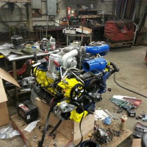
Good question.Why cant you just flip the 99 exhaust manifold upside down??? Or would that place the turbo lower then what you want???
We'll see when its done.On Edit: pretty sweet build you have going here...
I thought about using those too. I don't think the depth is any different.We use to use outlets kinda like you are putting in your truck at my previous job. The ones we used were a lot smaller the only downside is they are not covered like the one you have pictured. This may help you with some room issues if needed. Here is a link to one like we had.
http://www.newark.com/qualtek-elect...lar Products&MER=PPSO_N_P_EverywhereElse_None