H&S LPFP Upgrade kit review and install.

jcain

New member
Joined
Jul 14, 2013
Messages
2,017
Reaction score
0
First off, the packaging was about as good as it gets. Not a scratch on anything and all parts were protected from intrusion, after all we all know our fuel systems are sensitive as hell already. Secondly, the craftsmanship on the one off parts is perfect in every sense.

IMAG0369_1.jpg


Onward:


1st and foremost, IF you have a TransferFlow or Titan tank, MAKE SURE you tell H&S that when you order, you'll see why later. Some of these pictures are mine, and some are H&S's, you can tell by how dirty mine is :).


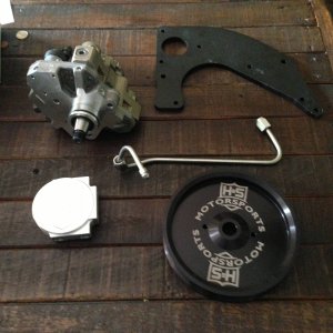
Step 1: Clean up the drool and get to work... Lay out all the parts and make sure you have everything. We can go ahead and knock out a BUNCH of preassembly before we ever have to step foot outside of the house. Make sure you get yourself some locktite/permatex thread sealer for all the pipe thread fittings.

H&S install directions has the exact info on which parts to put where on the filter bases, pump, and regulator so I'll just show pictures.

STEP%208.jpg


STEP%209%20(1).jpg


STEP%209%20(2).jpg


STEP%2015.jpg


STEP%2017.jpg


This is what each group of parts should look like when complete.

STEP%209%20(3).jpg


STEP%2015%20(2).jpg


STEP%2015%20(3).jpg


STEP%2017%20(2).jpg


IMAG0370.jpg


IMAG0371.jpg


IMAG0372.jpg
 
Last edited:

jcain

New member
Joined
Jul 14, 2013
Messages
2,017
Reaction score
0
Now it's time to head to the truck. Make sure you have a 1 1/4" socket to release the filter off the pump, or a set of 442 channellocks will do in a pinch, don't ask...
H&S has detailed instructions for this so I'll be basic. Disconnect all sensors, power, and 4 hoses. Have a bucket ready because it gets messy. Remove the factory pump assembly off the rail.

step%202.jpg


step%204%20(2).jpg


IMAG0374.jpg


This is where the larger fuel tank issue rares it's head. I'm sure you'll notice that it's going to be a tight fit. Where H&S has you put on a straight -8 to pushlok on the filter base we actually need a 90* here. Also, our hose routing will be a little different from base to pump, ie much shorter.

STEP%2012%20(2).jpg


Install the 1st bracket to the frame rail. Bypass the two hoses with the included piece. Now it's time to mount the base/pump/bracket up there, this will be a wrestle with the big tank as well... only put the left bolt in (the one to the rear of truck) and leave it loose. Now you'll need to twist the assembly clockwise and slip the feed line onto the filter base and get it locked in. Now you can install the second bolt and tighten it all down. Hook up the other factory line to the engine bay and your power now too.

IMAG0378.jpg


I have the factory upper intake and intercooler piping so this is a little different than the H&S install as theirs is on an aftermarket setup with MUCH more clearance. Remove the factory fuel lines to the secondary filter. Twist is clockwise till the nipples are point to the firewall and wiggle it out of the housing. Make sure you install the -6an to pushlock on the filter base now and have the hose already on. Position the 90* an fitting so its pointing straight down. You need to manhandle your engine and trans oil dipsticks a bit during this part so don't be scared. Position the new base so the nipples are towards the firewall and tilt the filter into the factory base and start twisting clockwise while pulling up on the dipsticks for clearance. Once you get to the intake piping, tilt the base towards you and keep twisting clockwise to get it into place. Don't be scared to apply a bit of pressure on the -an fitting, it'll be fine. Here's the outcome.

IMAG0376.jpg


Now mount the regulator on the firewall. Route the hose from the filter base to the regulator and cut hose to length and push-on the 90* -6 fitting. now put another *90 -6an fitting into the remaining hose and hook it to the other side of the regulator and route the hose down the backside of the motor with the other fuel lines all the way back to the LPFP. Cut to length and install the straight -6an push-lok fitting and install to filter base.

STEP%2018.jpg


STEP%2019.jpg


STEP%2019%20(2).jpg


Double check all your connections and fittings. Now it's time to purge the air out and get fuel to the motor. I had to cycle the key-on about 12 times before it started registering pressure, so don't be alarmed if it doesn't come right up. Start looking it all over during this process for leaks. I had a small one at the -an cap on the regulator, fix/tighten as needed. I had the regulator adjuster a hair over finger tight and that was about 15psi. Once you get to 15psi, start turning the adjustment clockwise until you get to 55-60psi. Go ahead and start the truck now and let it idle, adjust regulator if needed. Check for leaks again. Time for a beer now, or another.

IMAG0377.jpg


Here are some pictures for reference of ground clearance.

IMAG0379.jpg


IMAG0381.jpg
 
Last edited:

CATDiezel

New member
Joined
Dec 27, 2011
Messages
2,221
Reaction score
0
H&S... good people. Better writeups than I get from Caterpillar engineering.

I wish they would just rename to S&H and carry on normal opps.
 
Joined
Mar 7, 2014
Messages
628
Reaction score
0
Location
Central Illinois
Jcain, nice write up man! Definitely looks like an awesome quality product! Had one question for you though a little off topic. I saw you still have your CCV box installed with the plastic flex hose still on it. How do you have that all routed to the atmospher? Did you put an adapter and hose on the end of the flex hose to vent it further back in the truck? Was just curious because I wanted to keep the factory crankcase box and put a 90 fitting on it and run a hose to the back of the truck and cap off the intake port. A lot of people put the aftermarket CCV mods on it, but no one has talked about using the existing CCV box and running a hose from it. Just curious on how you did yours.
 

HS-MotorsportsZane

New member
Joined
Aug 8, 2013
Messages
469
Reaction score
0
Jcain, nice write up man! Definitely looks like an awesome quality product! Had one question for you though a little off topic. I saw you still have your CCV box installed with the plastic flex hose still on it. How do you have that all routed to the atmospher? Did you put an adapter and hose on the end of the flex hose to vent it further back in the truck? Was just curious because I wanted to keep the factory crankcase box and put a 90 fitting on it and run a hose to the back of the truck and cap off the intake port. A lot of people put the aftermarket CCV mods on it, but no one has talked about using the existing CCV box and running a hose from it. Just curious on how you did yours.

Kit almost on the website.........
 

Attachments

  • IMG_8660.jpg
    IMG_8660.jpg
    384 KB · Views: 137
Joined
Mar 7, 2014
Messages
628
Reaction score
0
Location
Central Illinois
Kit almost on the website.........

Awesome Zane! Any idea time frame on that or cost? So thatll use the stock CCV box and the flex hose, then go to your adapter and hose set up correct? The stock CCV box doesnt seem to be a restriction or a problem when its vented to atmosphere vs when there is a slight vacuum from the intake pulling gases through it correct? Sorry for the derail on the thread!!
 

Latest posts

Members online

No members online now.
Top