6.0 Fuel pressure question causing no start?

GRN250

Member
Joined
Jul 27, 2013
Messages
125
Reaction score
5
Location
Clarksville, TN
Should have searched prior to posting but found several videos of the 6.0 injector buzz test using different software/test instruments and my injectors sound identical to those on the videos. The "buzz" I am hearing is apparently normal. The AE software actually runs the test three consecutive times with the "buzz" between tests.
 
Last edited:

bismic

Member
Joined
Jul 3, 2011
Messages
340
Reaction score
8
Just an fyi:

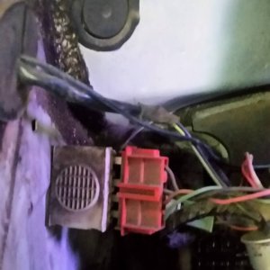
TROUBLESHOOTING CKP: first check for a broken o-ring causing an oil leak into the electrical connector.

To check the sensor: You can check the dark blue wire (pin 30) and orange wire (pin 41) at the PCM center connector (C1381c). Using a multimeter that reads hertz check across both wires while cranking, the CKP reading you should be getting from the sensor, is between 150 to 200Hz, directly proportional to engine cranking RPM when the engine is cranked over.
Testing the sensor AND the wiring: Check the resistance between the connector (C1381c) on the PCM Pin 30 (harness side) and Pin 41 (harness side). Resistance should be 300-400 ohms (sensor AND wiring resistance).
To check the WIRING ONLY: You can measure the resistance between the PCM engine connector (C1381c) pin 30, harness side and the CKP sensor pin 1, harness side; and between the PCM engine connector pin 41, harness side and the CKP sensor pin 2, harness side. Resistance on each test should be less than 5 ohms according to the manual, in reality the wiring resistance should be less than 0.5 ohms. CKP connector is C101.
 

GRN250

Member
Joined
Jul 27, 2013
Messages
125
Reaction score
5
Location
Clarksville, TN
The frequency between pins 30 & 40 ranged between 163-175 hz. Resistance between pins 30 & 40 measured 358.1 ohms (through crank sensor). Still haven't checked individual conductor resistance.
 

6.0 Tech

Well-known member
Joined
Sep 9, 2015
Messages
3,473
Reaction score
97
Location
Mesa, AZ
The frequency between pins 30 & 40 ranged between 163-175 hz. Resistance between pins 30 & 40 measured 358.1 ohms (through crank sensor). Still haven't checked individual conductor resistance.

Do you have a power probe? Put jumper wires between the 2 pins at the ckp/cmp sensors, send power down 1 wire from pcm, the other wire, tie a headlamp incandescent bulb into it to ground. Send power down one wire and make sure the bulb lights up bright. While it is lit up, wiggle the wiring harness in as many places as you can and see if there is any change in light output. Test lamps don’t have enough of a load to run this test. Hopefully that will help narrow this down…


Sent from my iPhone using Tapatalk
 

bismic

Member
Joined
Jul 3, 2011
Messages
340
Reaction score
8
These wires really don't carry much current when running since it is all magnetically driven (ie no power fed to them), but a load test on the wire might reveal a weak spot. The thing is that these sensors need a shielded signal and a load test won't identify anything there.
 
Last edited:

GRN250

Member
Joined
Jul 27, 2013
Messages
125
Reaction score
5
Location
Clarksville, TN
Have some longer leads ordered for my meter so waiting on them to perform the individual conductor resistance checks. Thanks for all your input and help.
 

GRN250

Member
Joined
Jul 27, 2013
Messages
125
Reaction score
5
Location
Clarksville, TN
New leads arrived and no issue found with crank position wiring. A used PCM, with same strategy, was acquired and installed. As soon as the truck reached the required hpop pressure, it fired off and ran as long as the throttle was slightly applied. Thanks for all your help and input to narrow down issues and provide required test points with expected readings.
 

bismic

Member
Joined
Jul 3, 2011
Messages
340
Reaction score
8
PCM's aren't usually the problem. Failed PCM's are identified typically by eliminating all other possibilities!

Glad you have it running.
 

Latest posts

Members online

Top