Aeroforce Scan Gauge

Tncoalroller88

New member
Joined
Feb 23, 2012
Messages
611
Reaction score
0
Location
Piney Flats, Tennessee
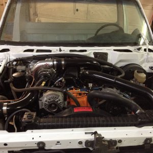
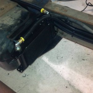
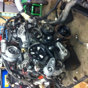
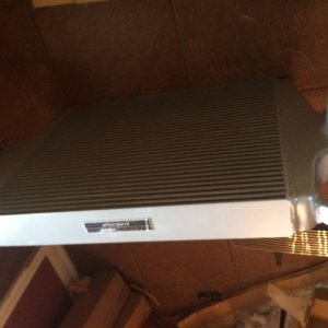
Does anyone know how to install the fuel pressure sensor kit into this thing im getting aggtivated with it. i have one set of instructions and their website says another. There instructions say 5volt and mine say 12 volt. iv got a few pics of this ****ty puzzle if anyone can help me id be greatful. Here are some pics of what came in my kit
IMG_20130602_171555_zpse7d5c2a3.jpg

IMG_20130602_171744_zps75213918.jpg

IMG_20130602_171657_zps666f56f6.jpg

IMG_20130602_172755_zps1ab2add7.jpg
 

Lethalthreat7.3

New member
Joined
Mar 24, 2013
Messages
313
Reaction score
0
Location
Denver, CO
PCM's operate from their inputs on 0 to 5vdc. This is done so that while starting and the alternator is recovering the loss from starting( dropping from say 13v to say 11.5v ) it doesn't cause any input issues to the PCM.
The way I understand it is to wire your reg to a "switched 12vdc" and install the resistor inline to the gauge.
The regulator should vary the output to the gauge from the 0.5vdc to 4.5vdc with the sensor inline to prevent a 12vdc feedback if you disconnect from the OBDII port.
 

Lethalthreat7.3

New member
Joined
Mar 24, 2013
Messages
313
Reaction score
0
Location
Denver, CO
You know after studying the confusing install diagram I think that the output from the regulator to the sensor is the 5vdc. The reg is wired to the switched 12vdc then sends 5vdc to the sensor. The output of the sensor will vary 0.5 to 4.5vdc and this goes to the gauge with the resistor inline/series.
You should be able to hook the reg up to 12vdc and see a 5vdc output which would then be wired to the sensor.(green from reg to red on sensor)
Sorry I should have studied it about 30secs longer before I posted the first time.
 

Tncoalroller88

New member
Joined
Feb 23, 2012
Messages
611
Reaction score
0
Location
Piney Flats, Tennessee
i see what your saying but the diagram doesnt show 5 volt coming out of the blue heat shrink wrapped thing anywhere. and if i hook 12volt to the 5 volt sensor then its fried on contact. it makes absolutely no sense to me at all im bout to say screw it and sell it all
 

4.0l sahara

New member
Joined
Dec 10, 2011
Messages
1,600
Reaction score
0
Location
shelton,ct
The green wire on the blue thing should be 5 volts out. That is the regulator they sell right? Ill buy it.
 

Tncoalroller88

New member
Joined
Feb 23, 2012
Messages
611
Reaction score
0
Location
Piney Flats, Tennessee
to tell u the truth i dont know if its the one they sell or if it just comes with the kit now or what.. but it states on the instructions everything going in and going out is 12 volt , when i thought it was supposed to be 12v in and 5 out. i thought the reg was supposed to be sold seperate cuz i didnt buy one the blue shrink wrapped thing was int the box
 

jaybuller

New member
Joined
Mar 4, 2012
Messages
507
Reaction score
0
I'm in for the resolution! I'm wanting this setup as well so I can get rid of my current Fp guage and just have 3 gauges instead of four....
 

jaybuller

New member
Joined
Mar 4, 2012
Messages
507
Reaction score
0
I'd be willing to bet its a typo on the schematic. That green wire labeled 12v is probably supposed to be 5v. Plug it up and see like 4.0sahara suggested. I just ordered mine from areoforce so I can let you know in a week or so.
 

Tncoalroller88

New member
Joined
Feb 23, 2012
Messages
611
Reaction score
0
Location
Piney Flats, Tennessee
im gonna have the thing tested tomorrow and see but i dunno if its a typo or not.. why would they sell the 5 volt converter seperate if it actually comes with the kit. i really am not a fan of aeroforce at all because of this. i mean come on put all the **** needed in a box and ship it to the customer with the correct directions how hard is that. people spend 300 plus bucks for this crap and they aint even got a guy that checks their **** bag schematics come on now what a crock. people complain bout glow shift pssshhh least their **** comes in one box with a detailed set of instrictions aeroforce is to cheap to even label their sensor box with a photo. what horse ****.... rant over
 

Tncoalroller88

New member
Joined
Feb 23, 2012
Messages
611
Reaction score
0
Location
Piney Flats, Tennessee
OK so I figured it out finally with the help of some guys on FTE.. The sensor kit I got is the revised version. And it actually used 12 volt and everything is included with the kit... Now that I got it working can someone tell me how they set it up to read correctly ? Also I put my little resistor In the beginning of the white wire that goes to the scan gauge is this right?
 

Tom S

Moderator
Joined
May 20, 2011
Messages
3,365
Reaction score
1
Where it says 12v on the diagram means connect the wire with the fuse to 12v nothing more.
 

Latest posts

Members online

No members online now.
Top