7.3 OBS Build: Gloria

Krause

New member
Joined
May 18, 2011
Messages
304
Reaction score
0
Location
BC Canada, and PA USA
Hey Guys,
Bringing this over from another forum, I hang out on here and at FTE equally, so figured I'de post this up for everyone to see. Ill try to keep a bit of a build thread going. I dont think anything I'll be showing is novel. Most of this is just researching and appreciated from other guy's builds.

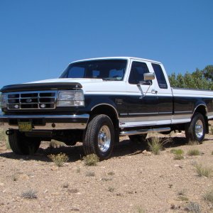
The truck is a 96 Ext cab, again some of you are familiar with this truck.

IMG_97211_zps6d8e2cce.jpg


The overview for the build is what many others have done:
-PIS 175/80 sticks
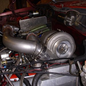
-Billet S366 with DIY mount
-Headstuds
-910 Springs
-T500 HPOP
-BTS valve body and likely a racerX torque converter.
-All sorts of maintenance while the motor is out, oil cooler rebuild, orings everywhere, injector cups, blah blah blah..

And the truck is already intercooled with efuel, Hydra with gearhead files at the moment.

Most of this stuff is already waiting for install as this has been in the works for some time. Only thing remaining is the injectors. Engine is getting pulled in a few weeks, and everything is getting done.

Arguably to biggest portion of this task is building the mount and uppipes.

I started with a big piece of angle, like this, 8x8 1/2 inch..

DSC_0018_zpse8371192.jpg


With no plasma cutter or torch to speak of, it was all zipcuts on the trusty Ryobi angle grinder... I had a T4 gasket, along with some of the measurements researched off Bills thread, and was able to lay out the "L bracket" . No pictures of the process but this is the end product.

DSC_0019_zps07b0572b.jpg

DSC_0020_zpsdf41ede6.jpg


The turbo holes are not wallowed out quite enough in those ^ pics, but I wanted to mount the turbo first so that I could see exactly where the edges needed to be so I didnt get carried away with the die grinder.

Onto the drill press it went.

DSC_0021_zps68c27044.jpg


And then cutting the threads for studs. I used 7/16'ths NC studs. They are fairly snug in the turbo mounting flange, so I was a bit apprehensive laying the holes out, there isnt a lot of tolerance before one stud prevents turbo from going on..

DSC_0023_zpsb06819e4.jpg


Studs in

DSC_0025_zpsee66d881.jpg


And then with a lot of relief, the turbo slid on. It was a bit tight, one stud needed a bit of coaxing to find the hole, surprising considering all my CNC equipment, bit it went on.

DSC_0027_zps9ae53925.jpg


DSC_0030_zps246cdcc8.jpg


Unfortunately I did not get any pictures making the bottom plate. For that, I did travel to a friends house and was able to use a cutting torch. Essentially I took a stock pedestal and traced the outline onto 1/2 inch plate, adjusted a bit for my liking, and copied the holes as well. Then cut it out.

Once that was done, I got the "L" bracket on the bottom plate where I wanted it on the mockup motor, and tacked the two together so that I could drill press the two together and avoid missing mark by 1/16.

Drilling out the 4 mounting holes for the L bracket

DSC_0032_zpse4f47cb6.jpg


And tapping the bottom plate, 1/2 inch NF in this case.

DSC_0033_zps56497e6f.jpg


Once that was done, I was able to mount both plates and get a look at that the turbo was going to look like in place.

DSC_0034_zpsbc94af2e.jpg

DSC_0035_zps11a0f9f0.jpg

DSC_0036_zps47fc1149.jpg


That's it for now, currently working on the up pipes. Hopefully some more pictures shortly.

-Andrew[/QUOTE]
 

Krause

New member
Joined
May 18, 2011
Messages
304
Reaction score
0
Location
BC Canada, and PA USA
I'll do a small update here.

Spent a considerable amount of time working some pieces to fit into the plate. to transition to the up pipes.

Dont mind to tacks, I have a harbour freight gas-less welder deal that dosnt do a nice job. These will be cleaned up on a tig shortly.
DSC_0038_zps74ece7d4.jpg


DSC_0039_zps872cf65d.jpg


Started mocking up the first side.

DSC_0040_zps295fc890.jpg


DSC_0041_zpscfc897d7.jpg


Then I didnt like how the bellow was right near the one transmission bellhousing bolt, was going to make for a tight fit. Also, I came across some for info that suggested I should keep the bellow higher if I could to help maintain room for the downpipe.

So I moved it up a bit.
DSC_0043_zps11389cc1.jpg


Some more nasty looking tacks.
DSC_0044_zps4c4450af.jpg


As it stands now, I have the remaining side partially mocked up, but I need to weld out the first side before I tack it in. Adding the other side is going to cut off access for a couple areas that will need to be sealed up with the tig. So I am going to get the first side welded up, come back, finish fitting the second side, and then have that welded up as well.

This is what the second side looks like.
DSC_0046_zps347b84a9.jpg

DSC_0047_zps8263ff5f.jpg


-Andrew

quick update,

Was able to make it out to a good friend's house who is gracefully helping me out with the welding on these pipes. If you saw some of the previous pictures, its goes without saying I left him more than a little contamination and booger tack welds to deal with. But, he did a awesome job with it, and we got the first side welded out so that I can finish fitting the second side.

We aired on the side of caution and he laid down a lot of material. I/we kinda preferred to see larger welds..

DSC_0049_zpsaee10524.jpg


DSC_0050_zpsf79fb819.jpg


DSC_0051_zps6872c858.jpg


DSC_0057_zpsfd17ce72.jpg


This was the nastiest gap I was worried about before hand...

DSC_0062_zps02856b84.jpg


DSC_0060_zps5997e21b.jpg


"grinding the crack"

DSC_0067_zps855165ea.jpg


DSC_0068_zps47ee2f28.jpg


So that is that. I couldnt be happier with how it turned out. I was a little discouraged with how the fitment was shaping up, but after seeing it all get made solid and sealed up, I'm far more confident in it. Unfortunately for my buddy, the limiting factor was having to deal with all my enormous flux core tack welds. They would really wreck havoc with the arch, not fun. But it sure is solid, good penetration into the 1/2inch plate, all good!

-Andrew
 

Krause

New member
Joined
May 18, 2011
Messages
304
Reaction score
0
Location
BC Canada, and PA USA
Have a short update.

Have been working on the oil drain for the turbo. I want to make something simple and effective with an oring. So I essentially started with a 1.5" piece of solid aluminum.

DSC_0073_zpsa7497af3.jpg


We have a small lathe at work that hasnt been used in ages. I dusted it off and tried it out, worked some kinks out and got to work. I havnt used a lathe since high school, so it took a bit of familiarizing again.

DSC_0078_zps53b3e54f.jpg


DSC_0079_zps36eb083a.jpg


DSC_0081_zpsaecc7753.jpg


The reduced area is .850, a touch smaller than the hole from the fuel pump. The large shoulder also shown here will be where a big ol fat o-ring will sit, and it will just seal to the top of the manifold...

DSC_0083_zpsb04ade2b.jpg


Then I got the drill set up

DSC_0085_zpsc5ccf5ca.jpg


DSC_0089_zps9d778264.jpg


Once it was all finished, it is drilled out to 5/8's ID, and I did a few passes to reduce the top diameter so that it fits on the 1.5" plate a bit better for welding. Made the low shoulder area shiny and that's it. Now I need to dry fit it along with the plate and fitting.

DSC_0092_zpsb95fb547.jpg


DSC_0091_zps13aa7fab.jpg


Pretty happy with the drain, was fun to make a custom one-off piece. Ill throw some pics up when it is fitted.
-Andrew

Alright, I have a couple pictures to post. I took more but apparently the flash wasnt working and they are just black smudges. Anyways, have been working on this oil drain.

Here is the plate with fitting that will get welded in.

DSC_0098_zpsf3zjk9tb.jpg


Here is the oil drain spout I lathed and already posted, this is how it sits in the valley

DSC_0099_zpshdzu5yca.jpg


Plate sits on top, and everything gets welded together

DSC_0100_zpsyw5x0vne.jpg


And I also got the passenger side up pipe done and tacked, ready to be taken to friends house to get made solid. Had more pictures of that but they were all dark. This is how it looks now.

DSC_0101_zpskvgm1fds.jpg


-Andrew
 

Krause

New member
Joined
May 18, 2011
Messages
304
Reaction score
0
Location
BC Canada, and PA USA
Well its finally time for an update. Have been working on the up pipes, I adjusted them from the last set of pictures a bit closer to the head. After taking several measurements, Im confident there will be ample room between the firewall now that they have been snugged up a bit. Then they sat a few days, and finally got made solid today.

DSC_0105_zps1rhd2lbn.jpg


DSC_0106_zpsmaou0vhi.jpg


DSC_0107_zpss3sgfgri.jpg


My fab work wasnt perfect, so there were some gaps to fill up at the union of everything. Because of that, it looks like there are some goobers here. But considering the gaps I managed to make, and everything being sealed up, Im super happy with them.

DSC_0108_zpsvuvhj0gj.jpg


A bit of work with the flapper and they will look fine.

Oil drain also got finished, here it is.

DSC_0109_zps8cx4yb1w.jpg


DSC_0110_zps8lbbvi3f.jpg


DSC_0111_zpsxxqskc2b.jpg


And thats it. Next step is to tinker away at getting these parts cleaned and painted.

-Andrew
 

Krause

New member
Joined
May 18, 2011
Messages
304
Reaction score
0
Location
BC Canada, and PA USA
Truck has not been insured since december, and all of a sudden I had a free weekend, it kinda snuck up on me. So no time like the present.

Pulled in into the garage I am using, which has a really effective industrial heater, thats a win, and a tight fit.

DSC_0112_zps7wlad25b.jpg


And to try to keep the place warm, I grabbed some plastic from lowes to try and seal it up. This actually turned out pretty funny..

DSC_0113_zpsjqwaiy8o.jpg


Looks like its coming through a portal or something!
DSC_0114_zpsivnndbhf.jpg


And from the back, the shop is giving birth
DSC_0144_zps7nj42yil.jpg


And it starts

DSC_0115_zpsxthyjwxm.jpg


DSC_0125_zpsfwzbjnzx.jpg


DSC_0131_zpswxuniaxo.jpg


DSC_0132_zpsssjyfomn.jpg


DSC_0133_zpsye3ykeay.jpg


Riffraff made me do, seriously though..

DSC_0134_zpsggme5p04.jpg


DSC_0135_zpsdhnzgqkx.jpg


DSC_0136_zpsiaqfhr1x.jpg


Shameless plug for Clay and the gang, maybe he will see this and sponsor me with some parts..

DSC_0139_zpsdzzoquog.jpg


And its out

DSC_0143_zpsdykgd6oq.jpg


Sitting off to the side

DSC_0147_zps0sefm3tl.jpg


And thats all. I pulled the HPOP off tonight after cleaning up. It is getting sent to Terminator tomorrow. And hopefully I'll pop the injectors out tomorrow night and get them sent to PIS. After that, I'll get to work painting, changing injector cups, and getting the headstuds put in while Im waiting to get things back.

As a side not, very happy I pulled the motor to do this deal. Still not sure how I would have gotten the turbo off. Obviously I know its possible, but I struggled with it with the engine out! Looking forward to a turbo setup I can remove very easily in the future.

-Andrew
 

Krause

New member
Joined
May 18, 2011
Messages
304
Reaction score
0
Location
BC Canada, and PA USA
Here goes an update before I fall behind on the pics. The box from riffraff shows up on Friday, after that, progress should be fast and furious.

Anyways, I've slogged through perhaps the slowest and most frustrating aspect of all this. Ive been cleaning for a week essentially.

These will serve as a rough before hand baseline set of photos..

DSC_0154_zpsyguoqmsv.jpg


DSC_0155_zpsegnate8p.jpg


DSC_0156_zps1i41gil9.jpg


Then I went and plucked out the valve train components. This is my first time getting into any of this, a good friend of mine said these really should be put back into their original location.

DSC_0167_zps6yctltyc.jpg


And injectors came out. These got sent off and are on their way back now! Came out really nicely, this is a veggi oil truck so I had to send them in to make sure they could be used for a build, but they checked out alright and was told they looked really good, so very happy with that.

DSC_0166_zpszlwtmf8c.jpg


There she is getting stripped down slowly.

DSC_0164_zpsizka44gw.jpg


(PS, the BEST 14.99 ive spent on this project was a bag of microfiber towels from Costco. At first I was hesitant to use them, but when I realized there is like 40 of them in the bag, I started grabbing a new one for every job (AKA every injector when I shipped them). Pretty sure it has saved me money vs blasting through rolls of paper towel that rip and fiber up everywhere).

Next came the headstuds.

DSC_0162_zpsg0dzl8lo.jpg


^Thats a really expensive layout of bolts :(. Its kinda ludicrous when you lay them out like that and realize they cost more than half a G.

Anyways, the ARP's come with generous sample packs of the torque lube stuff you are supposed to use now, it's very messy, use gloves (or put finger prints all over your girlfriends house for a few hours after completing job, even after washing your hands... ask me how I know).

The torque spec from FORD a final torque of 95 FT/LB's. This is done through 3 stages, and the final stage uses a different pattern than the first two. (These patterns can be found online easily enough, and the instructions from ARP include both of them as well).

How I opted to do it after reading up some:
1. I replaced each bolt one at a time following the pattern used in stages 1/2 (its a center-out theme), and torqued to the factory spec of 95 FT/Lbs. This will hold the head on just as tight as they ever were.

2. The final Torque spec for ARP is 125 Ft/Lbs. So after I had done each one of the 18 studs described in 1, I went through and torqued to 125 Ft/LBs using the 2nd torquing pattern (this is a bottom to top in rows theme).

3. After that, I waited 24 hours for things to settle and set (remember the gasket has never been this tight at this point). Then I set my torque wrench to 127 Ft/Lbs and re torqued according to step 2. I pretty much didnt get any movement on this step, just a couple bolts moved a pubic hair.

Repeat for the other head, and you are done. This isnt a 45 minute job, at least it wasnt for me. I wanted to make sure each thread/washer had enough torque lube and I wasnt missing a bolt/rushing, so it probly took 2.5 hours per head. That said, honestly guys, if this head gasket ever has a problem, wow... I dont know what I would do, buy a chevy?. 125 is TIGHT, and there is headstud every 3 inches or less it seams in every direction. 18 bolts is a lot of clamping power...

Here they are, you'll need a 12pt socket to install. Not that glamorous but look carefully, they are in there.

DSC_0180_zpslcumyrbi.jpg


After that, it was cleaning time, and boy did I clean. I'll shamelessly admit, that I eventually sacrificed a spare head for my Sonicare Electric toothbrush to assist in cleaning the nooks and crannies around the engine :-X21. The Girlfriend wasnt too pleased I was using a 150 dollar toothbrush to clean, but not too mad. She even helped a bit one night !

DSC_0182_zpsgyxsdst5.jpg


Got the oil cooler separated, thanks for the help on that, I beat it with a rubber mallet and it came apart.

DSC_0181_zpsm5ltgrna.jpg


And after several nights of degreaser, wire wheeling, purple power, repeat, etc etc... This is the one picture I seem to have of it cleaned up before any paint went on it.

DSC_0185_zpsxxc22vce.jpg


I used a DA sander to rough up areas I had access too as well. Any paint that was still around essentially survived a knotted wire wheel, a DA sander, or me sanding with a foam block, so I felt alright painting over what was left. I dont think it will last, but oh well, better than it was. I wasnt bringing this thing down to the bare block, so I did the best I could.
 

Krause

New member
Joined
May 18, 2011
Messages
304
Reaction score
0
Location
BC Canada, and PA USA
So the first thing to tackle was the oil pan. Mine was in great shape, very minimal surface rust, so I am keeping it in place. For the oil pan, I am using an epoxy paint made by Mastercoat. I wanted to try something other than POR15 a while back, and came across this stuff after Billy had mentioned it. Anyways Im really happy with it, the primer is epoxy based and will seal all by itself. But when you mix up the paint (satin black in this case), holy smokes look out, the smell of this stuff is FIERCE. I always get reminded of Anchorman, "its made from bits of real panther, so you know it's good", pretty much analogous to this, "its made from bits of real Satin, so you know it works."

Primer is a tame aluminum metallic colour, pretty decent looking all by itself (in fact Im leaving the front cover just done in this primer).

DSC_0186_zpsuvqahvjw.jpg


DSC_0187_zpsdpwgyqts.jpg


And a few of the accessories got this primer too..

DSC_0189_zpsdr8qggky.jpg


Then the epocy black went on. Took the shop about 3 days to air out after this, Im not joking.

DSC_0190_zpspx8p2ij2.jpg


Once it had set up for a few days and was hard enough that I was confident tape would pull any off, I got it taped up for spraying.

DSC_0191_zps1fph6ctl.jpg


DSC_0193_zpszyu6qi1k.jpg


DSC_0194_zpscjhyqrax.jpg


First coat of primer

DSC_0195_zpssymgogqr.jpg


DSC_0196_zpsfzjpb4nd.jpg


Second heavier coat of primer.

DSC_0197_zpsgjq89zip.jpg


DSC_0198_zpseas4khox.jpg


And after the colour. After reading another build, I was actually a big fan of the cast Iron he went with. I was originally planning an all aluminum theme, but since most of my piping is getting wrapped with black exhaust wrap, I decided to the monochrome theme with aluminum accents.

This is VHT Cast Iron Grey.

DSC_0199_zpsmdhcm0aw.jpg


DSC_0200_zpseipddxn3.jpg


I still need to paint the exhaust manifolds with higher temp paint, but I wanted to put a couple pieces on to get a sneak peak of how its roughly going to look. Still some stuff that needs to go on, I think it'll still come together a bit more.

DSC_0201_zpshfgcwd0w.jpg


DSC_0202_zpsxns0g0da.jpg


DSC_0203_zpslgztvyww.jpg


DSC_0204_zps66hyks9s.jpg


-Andrew
 

Krause

New member
Joined
May 18, 2011
Messages
304
Reaction score
0
Location
BC Canada, and PA USA
No oring groove cut on the oil return?

No, the shoulder on the drain is very wide and will seal against the top of the valley with a fat/squishy oring. It dosnt see any pressure or actual oil flow, so I didnt think it needed a grove for the oring. Should do its jub just fine sitting against both surfaces.
 

pullandpray

New member
Joined
Jan 20, 2015
Messages
333
Reaction score
0
O I got yea I know mine has an oring by that's because it doesn't have a shoulder to it.
 

zilla68

Active member
Joined
Jun 22, 2011
Messages
2,128
Reaction score
0
Location
Moore Oklahoma
your nuts if your not replacing those 4 big oil plugs in the heads and the 4 fuel plugs. I just did mine and my god what a pain that was.

looking good!
 

Latest posts

Members online

No members online now.
Top