Krause
New member
Hey Guys,
Bringing this over from another forum, I hang out on here and at FTE equally, so figured I'de post this up for everyone to see. Ill try to keep a bit of a build thread going. I dont think anything I'll be showing is novel. Most of this is just researching and appreciated from other guy's builds.
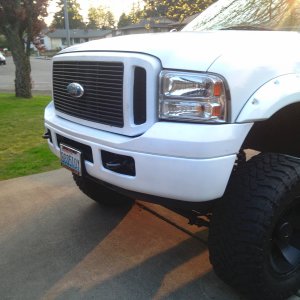
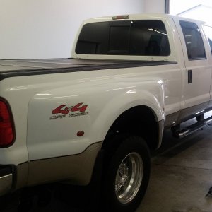
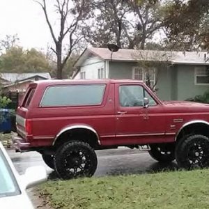
The truck is a 96 Ext cab, again some of you are familiar with this truck.

The overview for the build is what many others have done:
-PIS 175/80 sticks
-Billet S366 with DIY mount
-Headstuds
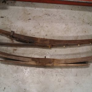
-910 Springs
-T500 HPOP
-BTS valve body and likely a racerX torque converter.
-All sorts of maintenance while the motor is out, oil cooler rebuild, orings everywhere, injector cups, blah blah blah..
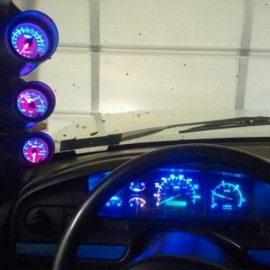
And the truck is already intercooled with efuel, Hydra with gearhead files at the moment.
Most of this stuff is already waiting for install as this has been in the works for some time. Only thing remaining is the injectors. Engine is getting pulled in a few weeks, and everything is getting done.
Arguably to biggest portion of this task is building the mount and uppipes.
I started with a big piece of angle, like this, 8x8 1/2 inch..

With no plasma cutter or torch to speak of, it was all zipcuts on the trusty Ryobi angle grinder... I had a T4 gasket, along with some of the measurements researched off Bills thread, and was able to lay out the "L bracket" . No pictures of the process but this is the end product.


The turbo holes are not wallowed out quite enough in those ^ pics, but I wanted to mount the turbo first so that I could see exactly where the edges needed to be so I didnt get carried away with the die grinder.
Onto the drill press it went.

And then cutting the threads for studs. I used 7/16'ths NC studs. They are fairly snug in the turbo mounting flange, so I was a bit apprehensive laying the holes out, there isnt a lot of tolerance before one stud prevents turbo from going on..

Studs in

And then with a lot of relief, the turbo slid on. It was a bit tight, one stud needed a bit of coaxing to find the hole, surprising considering all my CNC equipment, bit it went on.


Unfortunately I did not get any pictures making the bottom plate. For that, I did travel to a friends house and was able to use a cutting torch. Essentially I took a stock pedestal and traced the outline onto 1/2 inch plate, adjusted a bit for my liking, and copied the holes as well. Then cut it out.
Once that was done, I got the "L" bracket on the bottom plate where I wanted it on the mockup motor, and tacked the two together so that I could drill press the two together and avoid missing mark by 1/16.
Drilling out the 4 mounting holes for the L bracket

And tapping the bottom plate, 1/2 inch NF in this case.

Once that was done, I was able to mount both plates and get a look at that the turbo was going to look like in place.


That's it for now, currently working on the up pipes. Hopefully some more pictures shortly.
-Andrew[/QUOTE]
Bringing this over from another forum, I hang out on here and at FTE equally, so figured I'de post this up for everyone to see. Ill try to keep a bit of a build thread going. I dont think anything I'll be showing is novel. Most of this is just researching and appreciated from other guy's builds.
The truck is a 96 Ext cab, again some of you are familiar with this truck.
The overview for the build is what many others have done:
-PIS 175/80 sticks
-Billet S366 with DIY mount
-Headstuds
-910 Springs
-T500 HPOP
-BTS valve body and likely a racerX torque converter.
-All sorts of maintenance while the motor is out, oil cooler rebuild, orings everywhere, injector cups, blah blah blah..
And the truck is already intercooled with efuel, Hydra with gearhead files at the moment.
Most of this stuff is already waiting for install as this has been in the works for some time. Only thing remaining is the injectors. Engine is getting pulled in a few weeks, and everything is getting done.
Arguably to biggest portion of this task is building the mount and uppipes.
I started with a big piece of angle, like this, 8x8 1/2 inch..
With no plasma cutter or torch to speak of, it was all zipcuts on the trusty Ryobi angle grinder... I had a T4 gasket, along with some of the measurements researched off Bills thread, and was able to lay out the "L bracket" . No pictures of the process but this is the end product.
The turbo holes are not wallowed out quite enough in those ^ pics, but I wanted to mount the turbo first so that I could see exactly where the edges needed to be so I didnt get carried away with the die grinder.
Onto the drill press it went.
And then cutting the threads for studs. I used 7/16'ths NC studs. They are fairly snug in the turbo mounting flange, so I was a bit apprehensive laying the holes out, there isnt a lot of tolerance before one stud prevents turbo from going on..
Studs in
And then with a lot of relief, the turbo slid on. It was a bit tight, one stud needed a bit of coaxing to find the hole, surprising considering all my CNC equipment, bit it went on.
Unfortunately I did not get any pictures making the bottom plate. For that, I did travel to a friends house and was able to use a cutting torch. Essentially I took a stock pedestal and traced the outline onto 1/2 inch plate, adjusted a bit for my liking, and copied the holes as well. Then cut it out.
Once that was done, I got the "L" bracket on the bottom plate where I wanted it on the mockup motor, and tacked the two together so that I could drill press the two together and avoid missing mark by 1/16.
Drilling out the 4 mounting holes for the L bracket
And tapping the bottom plate, 1/2 inch NF in this case.
Once that was done, I was able to mount both plates and get a look at that the turbo was going to look like in place.
That's it for now, currently working on the up pipes. Hopefully some more pictures shortly.
-Andrew[/QUOTE]
 . Its kinda ludicrous when you lay them out like that and realize they cost more than half a G.