YoungMT Hick
New member
So I recently replaced the front hub thinking that was my issue and then after replacing that found out it was my upper ball joint instead. Well now I have a new hub and balljoints.
Yes, Now I know it wasn't the wheel bearing, $250 learning lesson, but now I know I have a new hub and balljoints.

Parts:
From Hub: Rock Auto, Timken P/N TMSP940200 $209
Ball Joints: EBAY, American UnderCar, item #151285409905 XRF Balljoints $129
Upper: K80026
Lower: K8607T
Front Axle U Joint: Napa P/N 374 $48
Grease $6

Tools:
Snap Ring Pliers: Napa SER 3492 (They have to be long and thing to get between the hub and axle shaft)
Ball Joint Press
34MM : Lower Balljoint Nut
28MM : Upper Balljoint Nut
21MM : 2 x Brake Caliper mounting bolts, 4 x Hub mounting Bolts
Torx T27 (HUB)
8MM wrench
1. Place front axle on jack stands, Left and right side.
2. Disconnect Drag link from knuckle by removing cotter pin and locking plate. lossen the nut and tap out with a hammer, preventing damaging the threads. Support the drag link with a spare jack stand or tie it up.
3. Remove brake caliper by removing the two 21MM bolts and hang caliper from coil spring, preventing pinching the brake line.
4. Remove Disc Brake Rotor.
5. Remove auto/lock hubs (T27 x 3). This is held in there by the three bolts and an O-Ring that seals the hub. Carefully pry out if needed.
6. Clean grease from inside the hub and remove the snap ring from the axle. This was one of the hardest parts of the process. Helps using the snap ring pliers and a small pick at the same time to pull out.
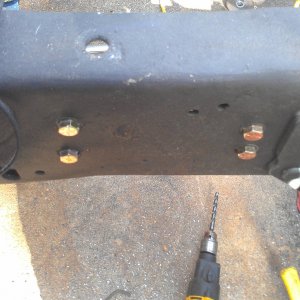
7. Remove the four mounting bolts on the hub that are inside the knuckle (21MM). Turn the knuckle to either side to help in removing the nuts.
8. Remove the three 8MM bolts that hold the ABS sensor on the knuckle and the coil spring mount. The allen head bolt on the hub stays there. Disconnect the ABS line connector that is on the wheel well liner near the firewall.
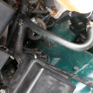
9. Remove the vacuum line from the upper left of the hub.
10. Remove the hub and dust shield from the knuckle. Use plenty of WD40 or PB Blaster ahead of time to help out with this. Helps to tap the hub side to side and eventually you can get a Prybar in between the Hub and Knuckle. The hub will stick due to rust and an O-Ring that is internal on the knuckle.
11. Remove the axle from the Knuckle and axle housing. It is not held in by any C-clips just pulls out. All you tube videos show it being super simple, well its Not. PITA. The black piece you will be seeing on the axle is a seal and will come out when the axle comes out. It helps to hit the back of the axle with a extension and hammer. Once you get the axle free'd it may be pulled out, if it still doesn't work there is one place you can pry on the axle. that is near the inner C on the axle. Where the dust shield is that normally falls out on most axles there is a little shoulder to the axle shaft. Pry there. Most likely you will damage the rubber piece on the axle but that is also just a dust shield. You will find that the inner axle tube is dry so no real big worry. The Axle has a Black plastic washer on the inner portion of the axle, acts as a dust shield? should come out with the axle, if not look down the axle tube for it.
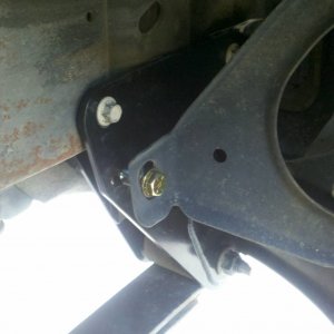
12. Remove the upper Knuckle balljoint nut (28MM) by removing the cotter pin and loosening the nut till flush with the end of the threads. (catches the knuckle once it falls free)
13. Remove the lower balljoint nut using the 34MM socket.
14. Using a pickle fork drive it between the Knuckle and C-section of the axle causing the Knuckle to fall, Finally remove the knuckle and transfer to a bench.
15. Remove the snap ring on the lower balljoint. Using the Balljoint press kit, start by removing the lower balljoint. I had to get a piece of 3" pipe 3" long as the catch can for the lower balljoint. Most kits wont have a piece long enough to to fit over the lower balljoint. I used an impact and WD40 to get the lower out.
16. Remove the upper balljoint by running the balljoint press through the lower balljoint and press upwards on the upper balljoint. Kit had enough tools to get the upper balljoint out.

17. Obviously this is a great time to clean and paint everything so now do it if you so desire.
18. Install the upper balljoint by lubing everything up with WD40, Set the Balljoint inplace set the press over the top of the balljoint to where the balljoint threads go through onne end of the press and the received end has a space and a cap. this will pull the balljoint into the socket, Again used an impact to tighten everything up. For the top balljoint, add some extra grease to the joint, install the rubber cap on the top and then remove the zerk and install the plug. The balljoint cannot be installed with a zerk due to the clearance between the u-Joint and the Zerk. Upper Balljoint will not use the provided snap ring they give you. If you compare the old Balljoint to the New on they are the same length.

19. Lower balljoint, same idea as the top. You can leave the Zerk Fitting installed. Install the snap ring on the lower balljoint when installed.


20. Change the U-Joint in the axle if so desired. The U-Joint is held in with C Clips in the inner portion of the U-Joint. Remove the 4 C Clips using a flat head and hammer. Next tap the stub shaft to one side to have the shaft slide to one side and pus the U-Joint Cap off. Remove both caps and set aside the stub shaft. Next hit the U-Joint to one side to get the caps off the U-Joint on the Long Shaft side.

21. Installing the U-Joint can be done by removing the U-Joint caps, sliding it into place and tapping in the caps with a hammer and then installing the C-Clips.

22. Install the knuckle on the axle, XRF gives you the torque specs, install the knuckle and tighten the upper nut finger tight. The lower balljoint uses a defected thread locking nut. You will notice it only threads on part way. when you tighten it the threads on the nut will straighten and keep the nut tight. XRF states tighten the lower balljoint to 35 Ft/Lbs, Upper to 70 Ft/Lbs install cotter pin, tighten lower balljoint to 150 Ft/Lbs. The knuckle should feel tight to move left to right and have no up and down movement.
23. Install the Hub onto the Knuckle along with the dust shield. Use grease on all O-Rings and inner surfaces. Tighten the hub mounting bolts (21MM) to 50Ft/Lbs (Hanes Manual). The new hub I got did not come with new mounting studs. So I had to get them out of the old one, again PITA. Using Double nut, heat and a hammer I was able to get them out. Clean them up and install using thread locker.


24. Install snap ring (PITA). Grease up the interior of the hub, install outer locking hub, install Vacuum line, Disc Brake rotor, Caliper, Wheels, and lower truck.
25. Hope you don't have any left over parts.
Overall not that hard. Hardest parts were getting the nuts off for the first time and getting that damn snap ring out. Don't know how much money I saved not taking it to ford but glad I was able to do it myself. I wrote this to help clearify some things. Youtube helped out a lot but most were of 1999-2003 axles. Their locking hub is a little different and to help point out the spots that are a little tough. Hope this helps some of you.
Yes, Now I know it wasn't the wheel bearing, $250 learning lesson, but now I know I have a new hub and balljoints.
Parts:
From Hub: Rock Auto, Timken P/N TMSP940200 $209
Ball Joints: EBAY, American UnderCar, item #151285409905 XRF Balljoints $129
Upper: K80026
Lower: K8607T
Front Axle U Joint: Napa P/N 374 $48
Grease $6
Tools:
Snap Ring Pliers: Napa SER 3492 (They have to be long and thing to get between the hub and axle shaft)
Ball Joint Press
34MM : Lower Balljoint Nut
28MM : Upper Balljoint Nut
21MM : 2 x Brake Caliper mounting bolts, 4 x Hub mounting Bolts
Torx T27 (HUB)
8MM wrench
1. Place front axle on jack stands, Left and right side.
2. Disconnect Drag link from knuckle by removing cotter pin and locking plate. lossen the nut and tap out with a hammer, preventing damaging the threads. Support the drag link with a spare jack stand or tie it up.
3. Remove brake caliper by removing the two 21MM bolts and hang caliper from coil spring, preventing pinching the brake line.
4. Remove Disc Brake Rotor.
5. Remove auto/lock hubs (T27 x 3). This is held in there by the three bolts and an O-Ring that seals the hub. Carefully pry out if needed.
6. Clean grease from inside the hub and remove the snap ring from the axle. This was one of the hardest parts of the process. Helps using the snap ring pliers and a small pick at the same time to pull out.
7. Remove the four mounting bolts on the hub that are inside the knuckle (21MM). Turn the knuckle to either side to help in removing the nuts.
8. Remove the three 8MM bolts that hold the ABS sensor on the knuckle and the coil spring mount. The allen head bolt on the hub stays there. Disconnect the ABS line connector that is on the wheel well liner near the firewall.
9. Remove the vacuum line from the upper left of the hub.
10. Remove the hub and dust shield from the knuckle. Use plenty of WD40 or PB Blaster ahead of time to help out with this. Helps to tap the hub side to side and eventually you can get a Prybar in between the Hub and Knuckle. The hub will stick due to rust and an O-Ring that is internal on the knuckle.
11. Remove the axle from the Knuckle and axle housing. It is not held in by any C-clips just pulls out. All you tube videos show it being super simple, well its Not. PITA. The black piece you will be seeing on the axle is a seal and will come out when the axle comes out. It helps to hit the back of the axle with a extension and hammer. Once you get the axle free'd it may be pulled out, if it still doesn't work there is one place you can pry on the axle. that is near the inner C on the axle. Where the dust shield is that normally falls out on most axles there is a little shoulder to the axle shaft. Pry there. Most likely you will damage the rubber piece on the axle but that is also just a dust shield. You will find that the inner axle tube is dry so no real big worry. The Axle has a Black plastic washer on the inner portion of the axle, acts as a dust shield? should come out with the axle, if not look down the axle tube for it.
12. Remove the upper Knuckle balljoint nut (28MM) by removing the cotter pin and loosening the nut till flush with the end of the threads. (catches the knuckle once it falls free)
13. Remove the lower balljoint nut using the 34MM socket.
14. Using a pickle fork drive it between the Knuckle and C-section of the axle causing the Knuckle to fall, Finally remove the knuckle and transfer to a bench.
15. Remove the snap ring on the lower balljoint. Using the Balljoint press kit, start by removing the lower balljoint. I had to get a piece of 3" pipe 3" long as the catch can for the lower balljoint. Most kits wont have a piece long enough to to fit over the lower balljoint. I used an impact and WD40 to get the lower out.
16. Remove the upper balljoint by running the balljoint press through the lower balljoint and press upwards on the upper balljoint. Kit had enough tools to get the upper balljoint out.
17. Obviously this is a great time to clean and paint everything so now do it if you so desire.
18. Install the upper balljoint by lubing everything up with WD40, Set the Balljoint inplace set the press over the top of the balljoint to where the balljoint threads go through onne end of the press and the received end has a space and a cap. this will pull the balljoint into the socket, Again used an impact to tighten everything up. For the top balljoint, add some extra grease to the joint, install the rubber cap on the top and then remove the zerk and install the plug. The balljoint cannot be installed with a zerk due to the clearance between the u-Joint and the Zerk. Upper Balljoint will not use the provided snap ring they give you. If you compare the old Balljoint to the New on they are the same length.
19. Lower balljoint, same idea as the top. You can leave the Zerk Fitting installed. Install the snap ring on the lower balljoint when installed.
20. Change the U-Joint in the axle if so desired. The U-Joint is held in with C Clips in the inner portion of the U-Joint. Remove the 4 C Clips using a flat head and hammer. Next tap the stub shaft to one side to have the shaft slide to one side and pus the U-Joint Cap off. Remove both caps and set aside the stub shaft. Next hit the U-Joint to one side to get the caps off the U-Joint on the Long Shaft side.
21. Installing the U-Joint can be done by removing the U-Joint caps, sliding it into place and tapping in the caps with a hammer and then installing the C-Clips.
22. Install the knuckle on the axle, XRF gives you the torque specs, install the knuckle and tighten the upper nut finger tight. The lower balljoint uses a defected thread locking nut. You will notice it only threads on part way. when you tighten it the threads on the nut will straighten and keep the nut tight. XRF states tighten the lower balljoint to 35 Ft/Lbs, Upper to 70 Ft/Lbs install cotter pin, tighten lower balljoint to 150 Ft/Lbs. The knuckle should feel tight to move left to right and have no up and down movement.
23. Install the Hub onto the Knuckle along with the dust shield. Use grease on all O-Rings and inner surfaces. Tighten the hub mounting bolts (21MM) to 50Ft/Lbs (Hanes Manual). The new hub I got did not come with new mounting studs. So I had to get them out of the old one, again PITA. Using Double nut, heat and a hammer I was able to get them out. Clean them up and install using thread locker.
24. Install snap ring (PITA). Grease up the interior of the hub, install outer locking hub, install Vacuum line, Disc Brake rotor, Caliper, Wheels, and lower truck.
25. Hope you don't have any left over parts.
Overall not that hard. Hardest parts were getting the nuts off for the first time and getting that damn snap ring out. Don't know how much money I saved not taking it to ford but glad I was able to do it myself. I wrote this to help clearify some things. Youtube helped out a lot but most were of 1999-2003 axles. Their locking hub is a little different and to help point out the spots that are a little tough. Hope this helps some of you.