Forums
New posts
Search forums
What's new
New posts
New media
New media comments
New profile posts
Latest activity
New showcase items
New showcase comments
Media
New media
New comments
Search media
Members
Current visitors
New profile posts
Search profile posts
Showcase
New items
New comments
Latest content
Latest reviews
Latest updates
Search showcase
Log in
Register
What's new
Search
Search
Search titles only
By:
New posts
Search forums
Menu
Log in
Register
Install the app
Install
Forums
West Point
The Library
1994-1997 OBS Series General
OBS Electric Fuel System
JavaScript is disabled. For a better experience, please enable JavaScript in your browser before proceeding.
You are using an out of date browser. It may not display this or other websites correctly.
You should upgrade or use an
alternative browser
.
Reply to thread
Message
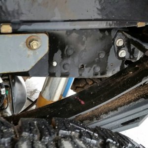
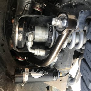
[QUOTE="Tom S, post: 362779, member: 623"] I decided to run Caterpillar filters on the pre pump side as well. I picked two different ones the 117-4089 which is a 150 micron filter water separator. [IMG]http://powerstrokenation.com/photopost/data/506/medium/DSCN0582.JPG[/IMG] I also selected the 131-1812 which is a 30 micron element and is what I am currently running. [IMG]http://powerstrokenation.com/photopost/data/506/medium/DSCN0482.JPG[/IMG] I had to modify the Stanadyne base to fit the keyway arrangement of the cat filters. I used a dremel tool and a rotary tool to cut in two new keyways. This was easy to do since the base is aluminum. [IMG]http://powerstrokenation.com/photopost/data/506/medium/DSC02460.JPG[/IMG] I also purchased a heater element for the pre-pump filter. The photo shows Stanadyne 34957 150 watt heater that goes in the top of the filter base and has a built in thermostat. [IMG]http://powerstrokenation.com/photopost/data/506/medium/DSCN0585.JPG[/IMG] This photo shows both filter assemblies side by side and the two micron high efficiency cat filter 1r-0750. [IMG]http://powerstrokenation.com/photopost/data/506/medium/DSCN0633.JPG[/IMG] I fabricated a bracket to mount the filters and pump inside the frame just aft of the transfer case. The angle bolts on the back side of the plate and then the angle sits on the flange of the frame rail. [IMG]http://powerstrokenation.com/photopost/data/506/medium/Mounting_plate.JPG[/IMG] This photo shows the filters and pump mounted to the bracket with the hoses connected. [IMG]http://powerstrokenation.com/photopost/data/506/medium/DSC024621.JPG[/IMG] I used ABA damage free hose clamps at all connections. These do not have slots in the band to dig into the hose. The edges of the bands also have a radius that does not cut into the hose. [IMG]http://powerstrokenation.com/photopost/data/506/medium/DSC02480.JPG[/IMG] [/QUOTE]
Insert quotes…
Verification
Post reply
Random media
Latest posts
10R140 failure
Latest: PSD-BLACK-CLOUD
Friday at 1:04 PM
2017+ 6.7 Aluminum Super Duty
2010 headunit
Latest: glog
Wednesday at 1:17 PM
6.4 Tech
D
Turning off the Auxiliary powertrain control module
Latest: donaldtfreeman
Tuesday at 10:43 AM
6.0 Tech & FAQ
4r100 P0715/P0717 trouble codes.
Latest: Tiha
Tuesday at 8:07 AM
7.3 Tech & FAQ
I must be getting old… Exhaust is too loud
Latest: ju015dd
May 4, 2025
6.0 Aftermarket
Members online
No members online now.
Forums
West Point
The Library
1994-1997 OBS Series General
OBS Electric Fuel System
Top