97 PSD to 58 C60

markfuga

Member
Joined
Apr 25, 2013
Messages
164
Reaction score
0
Location
Leesburg, VA
I have several items “in progress” and can’t seem to bring any single one to completion. I started the fuel system this week and have good enough progress to post so here are some pictures of where I’m at. I plan to pull the tank this weekend and give it the Por 15 restoration treatment so final connections will wait until that’s completed.

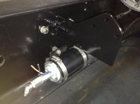
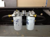
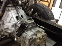
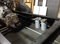
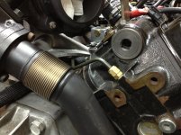
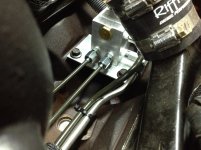
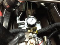
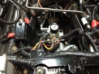
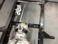
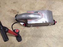
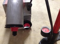
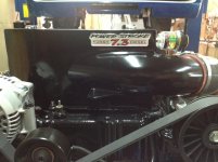
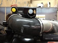
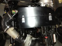
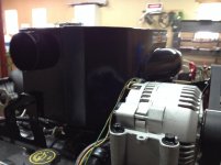
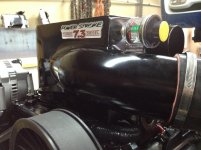
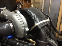
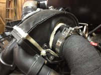
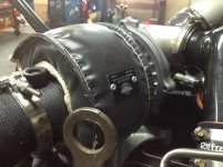
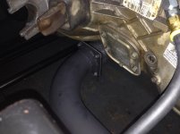
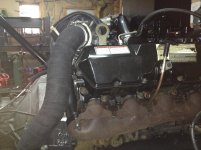
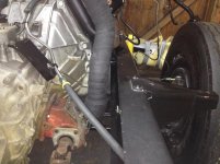
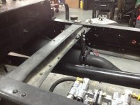
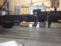
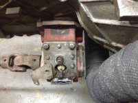
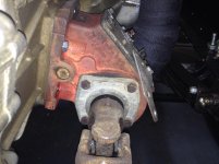
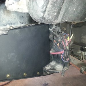
I made a simple bracket to mount the pump to the frame and another simple bracket for the filters. I abandoned the front steel lines because there’s no space to access that area (lower front of engine) after the body is set down on the frame. Instead, I made a new pair of steel lines to exit under the turbo, down the center of the transmission bell housing and off each side of the transmission case. Passenger side line will be the supply and the driver’s side is the return to the tank. I made a pair of matching brackets to bolt onto the transmission to support the lines as they transition to rubber lines over to the frame. I had some left over fiberglass sleeve from another project so I used it here since the lines pass under the hottest part of the turbo. Albeit, the new lines pose an issue if I want to remove the transmission for service, but I’ll deal with that when/if the time ever comes.
 

Attachments

  • IMG_0187.jpg
    IMG_0187.jpg
    701.2 KB · Views: 92
  • IMG_0190.jpg
    IMG_0190.jpg
    782.6 KB · Views: 98
  • IMG_0191.jpg
    IMG_0191.jpg
    889.1 KB · Views: 91
  • IMG_0192.jpg
    IMG_0192.jpg
    841.7 KB · Views: 90
  • IMG_0193.jpg
    IMG_0193.jpg
    1,002.7 KB · Views: 90

markfuga

Member
Joined
Apr 25, 2013
Messages
164
Reaction score
0
Location
Leesburg, VA
Couple more pics. Forgot to mention I made a bracket to lower the GPR down into the valley to make space for a CAI I'm building. Hope to finish it soon so I can post it too.
 

Attachments

  • IMG_0194.jpg
    IMG_0194.jpg
    888.6 KB · Views: 85
  • IMG_0195.jpg
    IMG_0195.jpg
    790.1 KB · Views: 86
  • IMG_0196.jpg
    IMG_0196.jpg
    924.5 KB · Views: 89
  • IMG_0197.jpg
    IMG_0197.jpg
    997.7 KB · Views: 87

mandkole

Active member
Joined
Jan 14, 2012
Messages
2,303
Reaction score
2
Location
Northwest
Cool, diggin on the detail...nice. You're right, the fuel lines will be problematic (if not impossible) to deal with during a tranny service so cross the fingers...

Maybe you've already mocked up the downpipe route and determined its ok, but to me the filter location is raising a flag. It looks to be cramped once a 3-4" pipe is there and it will be very hot. Regulated return systems run elevated fuel temps anyway and having them next to exhaust would add to heat gain.

Keep it up... its gonna be awesome when its done.
 

markfuga

Member
Joined
Apr 25, 2013
Messages
164
Reaction score
0
Location
Leesburg, VA
Thanks. The exhaust is going to route under the tranmission at the front and then down the drivers side frame. Reason is there's a PTO on the passenger side and a driveshaft from it to the pump for the dump hoist.
 

Vader's Fury

Active member
Joined
May 18, 2011
Messages
3,302
Reaction score
1
Location
Chesapeake City, MD
Any specific reason why you are putting the pto on the passenger side?

I usually install them on the driver side to prevent it from interfering with the exhaust.

Looks good but I wouldn't want to have to pull the trans with those fuel lines like that. Seems like you are making it harder than it needs to be. why not just run the lines direct to the frame rail and down to the filters.
 

markfuga

Member
Joined
Apr 25, 2013
Messages
164
Reaction score
0
Location
Leesburg, VA
The pump on the hoist tank is located on the passenger side with no provisions on the tank to move it to the drivers side so I'm stuck with staying on the passenger side. Coincidentally, the PTO lines up in a perfect line to the pump with where I place the engine (to the passenger side).

I'm not a big fan of running the fuel lines down the tranny; it was just the simplest solution. The space issue is due to the "double stacked" engine crossmembers. Since I kept the original, plus added the F250 crossmember to support the engine there's no space to access the lower front of the engine from under the truck. My other option would have been to run the lines down the front of the engine, then along the oil pan to the rear to allow access for a hose connection.

The fuel lines will come out easy enough if the trans needs to come out. It just means opening the fuel system and dealing with that mess as an added bonus. The lines unbolt from the fuel block and will slip straight back and off the engine. Of course the engine/tranny will need to be tilted to allow this to happen.
 

FrankTheTank

Active member
Joined
Oct 15, 2011
Messages
1,339
Reaction score
0
Location
Cecil County, MD
Your could leave a provision in the floor hump that u bolts so u can a sea the top of the trans to remove the fuel lines need be?

Also since your running the fuel lines up the back of the engine anyway, why not feed the read or the heads with banjo bolt fittings and clean ip the engine bay even more. But I know u would like to use your kit.
 

markfuga

Member
Joined
Apr 25, 2013
Messages
164
Reaction score
0
Location
Leesburg, VA
It’s a little too cold outside so I brought some of the project inside. Calibrating the temperature gauge is now checked off the list.

Unfortunately it wasn’t as easy as it could have been because the correct temp sensor is a ½ NPT and the 7.3 uses a 3/8 NPT. I didn’t want to fool around with couplers and adapters so I searched for an equivalent 3/8 NPT sensor. I spent many hours surfing the web (mostly Corvette sites came up in my searches) and found a close matched sensor (Wells TU66) which reads about 100 ohms higher throughout its range than the gauge is calibrated for. The fix is to add a resistor in parallel with the sensor, but figuring out the resistor size is the challenge. I cheated, went to Radio Shack and picked up a 1K ohm potentiometer. I wired it in parallel with the sensor, wired everything up to the battery and brought the pot of water to a boil (212 degrees). When the water was at a boil I adjusted the potentiometer until the needle on the gauge was just past the “halfway” point. I then read the potentiometer and determined a 470 ohm resistor was needed. I went back to Radio Shack, bought the resistor, attached it to the back of the gauge and ran the test again. The needle came off “cold” at 140 degrees and swept smoothly as the water came to a boil and landed just past the hallway point again. The needle was straight up/down in the center of the sweep at 200 degrees which should be normal operating temperature (I have the 203* thermostat).
 

Attachments

  • IMG_0205.jpg
    IMG_0205.jpg
    727.5 KB · Views: 77
  • IMG_0206.jpg
    IMG_0206.jpg
    844.3 KB · Views: 74

markfuga

Member
Joined
Apr 25, 2013
Messages
164
Reaction score
0
Location
Leesburg, VA
Another step forward today.

Earlier in the process I realized there wasn’t much room for an air cleaner and after much thinking I came up with this solution. I found the most available space was on top of the engine if I used a rectangular filter element. A little searching and I came across the AFE replacement filter for the 2011+ Ford 6.7L which they boast flows 650 CFM. I machined some ¾” aluminum flat bar to sandwich the filter seal, used 16ga sheet for the box, used the 3 mounting points for the stock engine cover (modified one) and added a filter minder and some decals for looks. Another feature is the 2 rectangular funnels that attach to the radiator support and the Spectra corrugated pipe that attaches between the funnels and filter box. Now it’s not only a filter box but also a CAI.

Two additional modifications to make it fit was making a bracket to lower the GPR down into the valley and moving the EBP sensor to the front cover (later 7.3 location).

I did some testing using pressure and vacuum to be sure the box was sealing properly. I was able to get about 8lbs of pressure before air escaped passed the seal which is acceptable. The vacuum test passed with flying colors. I attached the shop vacuum as seen in the pictures and burned paper at a smolder to produce lots of smoke. The smoke passed all around the box without the slightest hint of getting sucked in. I’m calling it a winner for now; the true test comes when I run it down the road.

Here’s a ridiculous number of pictures to show what I’m talking about.
 

Attachments

  • IMG_0107.jpg
    IMG_0107.jpg
    640 KB · Views: 74
  • IMG_0108.jpg
    IMG_0108.jpg
    577.2 KB · Views: 67
  • IMG_0109.jpg
    IMG_0109.jpg
    782.5 KB · Views: 72
  • IMG_0113.jpg
    IMG_0113.jpg
    702.7 KB · Views: 75
  • IMG_0114.jpg
    IMG_0114.jpg
    680.5 KB · Views: 71

markfuga

Member
Joined
Apr 25, 2013
Messages
164
Reaction score
0
Location
Leesburg, VA
more pics.
 

Attachments

  • IMG_0115.jpg
    IMG_0115.jpg
    601.7 KB · Views: 74
  • IMG_0117.jpg
    IMG_0117.jpg
    847.8 KB · Views: 69
  • IMG_0207.jpg
    IMG_0207.jpg
    667.1 KB · Views: 73
  • IMG_0209.jpg
    IMG_0209.jpg
    953.2 KB · Views: 78
  • IMG_0210.jpg
    IMG_0210.jpg
    765.3 KB · Views: 70

markfuga

Member
Joined
Apr 25, 2013
Messages
164
Reaction score
0
Location
Leesburg, VA
Finished the exhaust!

I re-made the down pipe again for the last time. When I tried setting the cab I found the previous down pipe build (number 3 I think) was too tight to the cab floor and just didn’t clear it. This time I made it a “block hugger”, wrapping tight around the back of the head, paralleling the up pipe on its way down and then back to the location I had it previously to go under the transmission.

The down pipe ends at a 4 bolt flange so it’s easily removed for any maintenance and the good news is the down pipe can be installed and removed from under the truck at anytime. The exhaust pipe is 3.5” and goes into a Walker 21470 muffler: known as the BTM (big truck muffler) on the message boards. It exits the muffler through a single 45 degree elbow.

I wrapped the down pipe with DEI exhaust wrap and covered the turbo exhaust housing with a blanket from PTP turbo. I chose to not wrap the up pipes for fear of cooking the bellows. Those IH bellowed up pipes are too expensive, so I didn’t want to risk them. I did have the Up pipes, y-collector, turbo housing and exhaust outlet ceramic coated. The exhaust pipe and muffler were painted with Rustoleum’s high heat BBQ paint (found at your local Home Depot).

The only remaining note worthy effort was machining the turbo exhaust outlet. I did an EBPV delete and then turned the inside diameter on the lathe and opened it to a little over 2.875” I also machined the angle the up pipe seals against to true the face and as a bonus this allowed the band clamp to have a tighter hold at the T-bolt (less gap).
 

Attachments

  • IMG_0220.jpg
    IMG_0220.jpg
    874.1 KB · Views: 77
  • IMG_0221.jpg
    IMG_0221.jpg
    1 MB · Views: 75
  • IMG_0222.jpg
    IMG_0222.jpg
    918.7 KB · Views: 74
  • IMG_0223.jpg
    IMG_0223.jpg
    608.6 KB · Views: 70
  • IMG_0224.jpg
    IMG_0224.jpg
    879.8 KB · Views: 80

markfuga

Member
Joined
Apr 25, 2013
Messages
164
Reaction score
0
Location
Leesburg, VA
couple more pics
 

Attachments

  • IMG_0225.jpg
    IMG_0225.jpg
    962.2 KB · Views: 69
  • IMG_0226.jpg
    IMG_0226.jpg
    1,003.7 KB · Views: 67
  • IMG_0227.jpg
    IMG_0227.jpg
    891.2 KB · Views: 68
  • IMG_0228.jpg
    IMG_0228.jpg
    1 MB · Views: 66
  • IMG_0229.jpg
    IMG_0229.jpg
    676.9 KB · Views: 69

markfuga

Member
Joined
Apr 25, 2013
Messages
164
Reaction score
0
Location
Leesburg, VA
Been kicking around ideas for how to arrange the gauges and finally decided to setup 3 pedestal mounted gauges: tachometer, Pyrometer and boost. These will mount under the dash, center behind the shifter. I wanted a tachometer that will work with the PCM and closely match the other two gauges I bought (Autometer Z series) so here’s what I did:

1. Buy cheap pedestal mount tachometer that’s 3.75 inch diameter
2. Take out the electronics from the new tach and throw them away
3. Tape a hooked piece of wire to the original tach’s needle and draw appropriate circle then cut carefully
4. Divorce the control board from the old tach and mount it where ever is convenient
5. Screw it all back together and take pictures

Opinions?
 

Attachments

  • IMG_0240.jpg
    IMG_0240.jpg
    549.2 KB · Views: 66
  • IMG_0241.jpg
    IMG_0241.jpg
    1 MB · Views: 63
  • IMG_0242.jpg
    IMG_0242.jpg
    890 KB · Views: 67
  • IMG_0243.jpg
    IMG_0243.jpg
    725.1 KB · Views: 64
  • IMG_0244.jpg
    IMG_0244.jpg
    532.3 KB · Views: 66

FrankTheTank

Active member
Joined
Oct 15, 2011
Messages
1,339
Reaction score
0
Location
Cecil County, MD
That's pretty sweet . This takes care of one of the hardest parts, getting the dash figured out and operate under the control of the newer engine and electronics in an old truck.
 

markfuga

Member
Joined
Apr 25, 2013
Messages
164
Reaction score
0
Location
Leesburg, VA
Many details worked on over the last couple weeks; too numerous to list. I’m very close to setting the cab down and plan to make a video before I set it to show everything I’ve done to fit the drivetrain into the chassis. Just for fun I made a 2 minute video of the old engine on the run stand.

http://www.youtube.com/watch?v=etrLZhctnAA
 

Latest posts

Members online

Top