Flow bench?
- Thread starter Buffalo444
- Start date
Charles
Well-known member
- Joined
- May 18, 2011
- Messages
- 2,729
- Reaction score
- 47
You've got the basic idea, but you need to look really close at an engine running and zoom way in.
What you have there still won't be accepted from what I can see.
I'm sick as a dog and have been over 100* for around 6 days now, so I may be retarded, but is that over 5700rpm???
If so, calm down, lol.
What you have there still won't be accepted from what I can see.
I'm sick as a dog and have been over 100* for around 6 days now, so I may be retarded, but is that over 5700rpm???
If so, calm down, lol.
Last edited:
ja_cain
Active member
- Joined
- Aug 10, 2013
- Messages
- 4,597
- Reaction score
- 2
Good stuff Charles! Thanks for posting that up.That diagram is the basic idea, but it will not run an IDM, except by blind chance, with that chance being like 1 in 10,000 that you happened to line everything up right.
In fact, looking closer, if you produced signals exactly like those, it would never run. 0% chance.
On Edit:
I thought I remembered one time arguing with people that the communications protocol between PCM and IDM would not support but XXX pw at XXXX rpm and had quickly generated the needed signals to show the limits of the com. protocol. Turns out it was still up on youtube, so, it just so happens that this is also the exact signal generation anyone needing to run a flow bench using a ford IDM (the preferred method) would need.
Look closely, because this is an accurate and real com link that would, and has run a 7.3 engine, as well as flowbench. I won't just spell out every last nook and cranny because that information was painstakingly earned and handed to me many years ago. Although I think it has all been stated in plain English since then, you are in fact wanting to build a flowbench, possibly to directly compete with those people. So, you need to do some legwork, but this is a proper, running com link I generated long ago.
https://www.youtube.com/watch?v=RfHF0hZdUZw
Sent from my SCH-I545 using Tapatalk
Charles
Well-known member
- Joined
- May 18, 2011
- Messages
- 2,729
- Reaction score
- 47
Still 4800rpm right?
You've got serious synchronization issues that a running engine are your only hope of finding.
Is the arduino a multi-processor chip?
You've got serious synchronization issues that a running engine are your only hope of finding.
Is the arduino a multi-processor chip?
I just changed the code to have a 500us FDCS off delay to match your duty cycle. The Arduino doesn't have a processor and the thought was it may be needed. The raspberry pi is similar but has a processor around $100.
Last edited:
ja_cain
Active member
- Joined
- Aug 10, 2013
- Messages
- 4,597
- Reaction score
- 2
I made an edit to my last that you should not miss.
Btw, excuse the slow speech, I think I had been so worn down by idiots at that point that it was affecting my ability to care enough to speak clearly, lol. The same morons that continue being morons today were up in arms adamantly explaining how they could tune a truck to run hellacious pulsewidth at clearly impossible rpm points. Ever notice how the same idiots come up with the really dumb sh*t?
Anyway, turns out that video provides this thread with a good view at a real IDM com link.
It's all good. The only thing I couldn't quite follow, while listening on my phone, was the pw numbers at the end. I'll watch it again in a quiet spot later when I have a chance. Thanks again for posting that up.
ja_cain
Active member
- Joined
- Aug 10, 2013
- Messages
- 4,597
- Reaction score
- 2
I just changed the code to have a 500us FDCS off delay to match your duty cycle. The Arduino doesn't have a processor and the thought was it may be needed. The raspberry pi is similar but has a processor around $100.
I thought I had two of those labjacks at work, but could only find one. Ill look again on Monday when I'm at work. If I can find the non-pro model, I'd be willing to send it to you as long as you promise to follow through on this project.
ja_cain
Active member
- Joined
- Aug 10, 2013
- Messages
- 4,597
- Reaction score
- 2
You've got the basic idea, but you need to look really close at an engine running and zoom way in.
What you have there still won't be accepted from what I can see.
I'm sick as a dog and have been over 100* for around 6 days now, so I may be retarded, but is that over 5700rpm???
If so, calm down, lol.
I hope you feel better soon! Not cool being sick like that around Christmas time. Btw, I calculated 3000 RPM for that last pick before your post. Of course, I'm not the sharpest tool in the shed, so my math could be off.
Charles
Well-known member
- Joined
- May 18, 2011
- Messages
- 2,729
- Reaction score
- 47
I think you need to keep CID and FDCS in the same routine. Those cannot be run in seperate routines and everything work out in my experience. They are tied at the hip.
You know the "off time" on the FDCS is in between injectors, and the injector pulsewidth is defined by the time that FDCS is high after the leading edge of each event right? You don't pick the low, you pick the high and the low is just what's left before the next injector at the rpm in question.
Building a flowbench, pulsewidth and shot count are the bible.
Charles
Well-known member
- Joined
- May 18, 2011
- Messages
- 2,729
- Reaction score
- 47
I hope you feel better soon! Not cool being sick like that around Christmas time. Btw, I calculated 3000 RPM for that last pick before your post. Of course, I'm not the sharpest tool in the shed, so my math could be off.
Sucks bad. Just got a positive Flu test at the hospital. Had to send the Fam away, which really sucks bad. Now it's just me, a cattle dog and a bag of Tamiflu...
Maybe it'll kick ass in time for Christmas.
Sucks bad. Just got a positive Flu test at the hospital. Had to send the Fam away, which really sucks bad. Now it's just me, a cattle dog and a bag of Tamiflu...
Maybe it'll kick ass in time for Christmas.
You need to increase your vitamin wild turkey intake to kill that off. About six shots and a hooded sweatshirt in the house, get it gone.
ja_cain
Active member
- Joined
- Aug 10, 2013
- Messages
- 4,597
- Reaction score
- 2
Sucks bad. Just got a positive Flu test at the hospital. Had to send the Fam away, which really sucks bad. Now it's just me, a cattle dog and a bag of Tamiflu...
Maybe it'll kick ass in time for Christmas.
I hate the flu (haven't had it in 8 years, knock on wood). The one time I took Tamiflu, it made me sicker than having the flu. I had to take care of my year old daughter who was sick at the same time and it was brutal. That was a good call to send the fam away.
You are the second guy that I have talked to lately that is feeling under the weather. A guy that I am trying to buy a 288xp chainsaw from on another site told me he has been feeling under the weather for the last few days. I bet it's the flu too.
Morgan@Midwest Diesel & Auto
New member
I think you need to keep CID and FDCS in the same routine. Those cannot be run in seperate routines and everything work out in my experience. They are tied at the hip.
You know the "off time" on the FDCS is in between injectors, and the injector pulsewidth is defined by the time that FDCS is high after the leading edge of each event right? You don't pick the low, you pick the high and the low is just what's left before the next injector at the rpm in question.
Building a flowbench, pulsewidth and shot count are the bible.
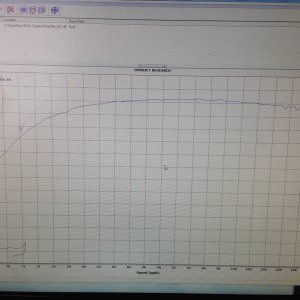
I am an idiot by the actual terms of what you are speaking. No code writing or program writing experience. But I see exactly what you are saying. And the difference between the video you posted and the picture below it.
Very simple as to why you can run X# pulses for X# ms while staying in between the FDCS lines all while it gets narrower at higher rpms....
All I have to say is, just run 30% nozzles and it makes it all better.... Lol. Everyone needs 5ms.... That they can't get...
Sent from my iPhone using Tapatalk
Morgan@Midwest Diesel & Auto
New member
Just build me a piezo controller and I'll be happy. I don't want to spend $150k...
Sent from my iPhone using Tapatalk
Sent from my iPhone using Tapatalk
ja_cain
Active member
- Joined
- Aug 10, 2013
- Messages
- 4,597
- Reaction score
- 2
Just build me a piezo controller and I'll be happy. I don't want to spend $150k...
Sent from my iPhone using Tapatalk
Piezo's are crazy fast. Fast enough to have multiple injection pulses per compression event.
Morgan@Midwest Diesel & Auto
New member
Piezo's are crazy fast. Fast enough to have multiple injection pulses per compression event.
I know. And the bench is super expensive....
Sent from my iPhone using Tapatalk


