What you REALLY wanted to know about SOI.

389sixpack

Moderator
Joined
May 18, 2011
Messages
259
Reaction score
0
Location
New Jersey
OK. I'm going to clean up this thread form all the "good" and "subscribed" and misc comments so it moves along better.

And BTW, you can subscribe by selecting subscribe from the thread tools drop-down box.


.
 

CamTom12

Member
Joined
Sep 14, 2011
Messages
821
Reaction score
0
Location
Huntsville, AL
OK. I'm going to clean up this thread form all the "good" and "subscribed" and misc comments so it moves along better.

And BTW, you can subscribe by selecting subscribe from the thread tools drop-down box.


.

I really don't want to derail here because I'm with what you're trying to do, but selecting subscribe and actually posting seem to be two different things in tapatalk.
 

jngreen

New member
Joined
May 21, 2011
Messages
1,083
Reaction score
0
Location
IN
I really don't want to derail here because I'm with what you're trying to do, but selecting subscribe and actually posting seem to be two different things in tapatalk.


Its two totally different things on a computer as well. If you subscribe to a thread, by clicking on thread tools, it will not show up under the "my threads/ replies" link. You have to click on the "user cp" link to check the threads that you subscribe to. Then the threads will only show up if there has been new posts in it since the last time you visited. You can click on the "view all subscribed threads" on the "user cp" page to see all of your subscriptions.

It is a very useful tool for someone who doesn't like to be a post whore, but likes to keep track of threads. In my case, I usually don't have much relevent info to add, but I like to learn, so I choose to subscribe.
 

ToMang07

Well-known member
Joined
Jan 25, 2012
Messages
6,561
Reaction score
174
Location
Mainah!
waiting%20for%20the%20draft.jpg
 

Power Hungry

Member
Joined
Jun 20, 2011
Messages
365
Reaction score
0
Location
Winder, GA
Hey all... I'm really sorry about the delay in posting. Corey and I have both been under the weather recently and we're just getting back in the saddle, so to speak. Not to mention that we're backed up quite a bit in the office as well. :doh:

Anyway, here is part 2 of our "PSD Tuning" series. I'll have part 3 up in another couple hours or so and then we'll open up for questions. I appreciate everyone's patience and hope that this is helpful and informative.

Thanks! :D
 

Power Hungry

Member
Joined
Jun 20, 2011
Messages
365
Reaction score
0
Location
Winder, GA
Part 2: The tuning hardware.

Part 2: The tuning hardware. Dynos, testing equipment, emulators, and how they all work together:

Over the last 15 years, how we tune the 7.3L Power Stroke has improved considerably. Not only has the tuning hardware and software seen significant advancements, but the diagnostic equipment has also improved and provides a much greater wealth of feedback data than anything we could have hoped for in the '90s. Tuning for the 7.3L (or any other EEC processor based vehicle) is at a distinct advantage because these ECMs can be "live" tuned. This means that we can actually make changes to the tables and functions as the vehicle is running. This SIGNIFICANTLY reduces the amount of time spent tuning. When you consider that we can change in seconds what would most likely take days or even weeks to tune using the "chip" method, you can see why live tuning is the preferred method of tuning for any heavily modified vehicle and is even helpful on modestly modified vehicles. Coupled with high speed datalogging, we can immediately see how individual changes affect the vehicle performance. Later vehicles (2003+) such as the 6.0L, 6.4L, 6.7L and other applications don't offer the flexibility of live tuning (at least not inexpensively), but most can be reflashed pretty quickly with only a minute or two between dyno or street runs. However, since this thread deals specifically with the 7.3L, we're going to remain on that topic.

Live tuning on the 7.3L requires, at the very minimum, the use of some sort of memory emulator connected to a PC/Laptop running a related software in which changes can be made to the memory image. Ideally, datalogging software will also be used to monitor specific parameters related to the changes being made, although for certain tuning aspects such as shifting, datalogging may not be necessary. For more involved setups, additional testing equipment may be utilized. High speed Cylinder Pressure (CP) testing equipment is used by more advanced/experienced tuners to get a clearer picture of what is happening inside the cylinders during the combustion process. On a diesel, this is especially important since there is no specific, identifiable, direct relation between the Start of Injection (SOI) and Start of Combustion (SOC) and the only way to accurately determine a proper combustion cycle is to monitor cylinder pressures in relation to crankshaft rotation. Monitoring of exhaust temps is also critical, but since most trucks have a pyrometer installed already this is generally pretty well covered. Below is a breakdown of the popular tools used in tuning:

The Dyno: I'm pretty sure that by now everyone knows what this is. The dynamometer (or "dyno" as it is commonly referred to) is a device that measures the acceleration of a specific mass and uses that information to generate a power curve measured in HP (or sometimes WATTS in the case of foreign dynos). There are several types of dynos available for testing:
  • Engine Dyno: This type of dyno is set up to measure HP from an engine directly at the flywheel. This requires special setups for different engines to mate the engine to the dyno, along with additional equipment for cooling, exhaust, fuel, and other requirements. The advantage to this setup is that it allows the testing facility much greater control over the testing parameters and measure the power directly at the engine without having to deal with additional driveline losses through the transmission, transfer case, and axles. This type of dyno is generally used by engine manufacturers and professional racing facilities (such as NASCAR) in order to provide accurate HP numbers for specific engine configurations. Engine dynos are typically a "load" type dyno and frequently use a water brake to apply parasitic load to the engine, although some use an eddy current load cell to provide parasitic load. See the section below on "Load Dyno" for more information.

  • Chassis Dyno: This type of dyno allows for a vehicle to be situated so that the drive wheels spin rotating assembly. This is what most performance shops and mobile dyno services use. Chassis dynos are available in both "Load" type and "Inertia" type, with differences explained below. The disadvantage to most chassis dynos is that the HP is measured at the wheels and will always be lower than flywheel HP by sometimes as much as %30, depending on transmission type (Manual or Auto, 2WD or 4WD) and wheel and tire configurations. Larger/heavier wheels and tires provide additional parasitic losses and will regularly exhibit lower numbers than the same vehicle with smaller/lighter wheels and tires. Also, automatic transmissions will see larger parasitic losses than a similarly equipped vehicle with a manual transmission. Obviously, the biggest advantage to a chassis dyno is that you can run the vehicle without having to remove the engine, which just isn't feasible in most situations. Another advantage is that while you may not have an accurate measurement of power at the flywheel, you know exactly what is being put to the ground. This, combined with vehicle weight, can provide a pretty reasonable idea of what your ideal 1/4 mile runs will be. One final advantage of a chassis dyno is a matter of safety. With the vehicle strapped to a dyno, it's a considerably safer place to make changes in tuning than what you'd find on even the most deserted of streets. Plus, with a load dyno you can even simulate various road and driving condition, even simulating pulling a trailer. Since chassis dynos are the most popular and prevalent configuration, this provides a fairly common platform for individuals to compare performance and power numbers. Just keep in mind that no two dynos are going to give the exact same power numbers and these numbers can vary greatly between load dynos and inertia dynos as well as numbers between different dyno manufacturers. Popular chassis dynos are DynoJet, Mustang, SuperFlow, and Dyno Dynamics, with Mustang, SuperFlow and DynoDynamics being primarily load type dynos and DynoJet being primarily an inertia type dyno.

  • Inertia Dyno: In the 1990s and early 2000s, inertia dynos were the most common dyno configuration with DynoJet model 248c probably being the most popular dyno available during that era. Inertia dynos use 1 (or more) weighted drum(s) to provide a specific load against which the vehicle must accelerate. HP is measured based on the amount of time it takes to accelerate the roller(s) and then is output as a power curve over time, vehicle speed, or engine speed. For light, naturally aspirated or supercharged vehicles, this often provides accurate and consistent power numbers. However, for heavier turbocharged vehicles, inertia dynos may not be consistent or accurate as the inertial weight (usually around 4,000 Lbs.) often doesn't provide enough load to simulate a 7,000 to 10,000 Lb. vehicle. This frequently results in inadequate boost generation and lower power numbers. There is also some debate over the accuracy of these dynos at higher power numbers, but that is outside the scope of this dicussion.

  • Load Dyno: A load dyno can be configured as a load cell alone, or a load cell combined with an inertial mass. Most engine dynos use a load cell by itself while most chassis dynos are a load and inertia combination. Load cells are used to provide a variable load in order to test power under different situations. Early engine dynos used a water brake to absorb power while most later engine and chassis dynos use an eddy current (electrical) brake absorption unit. A load dyno offers significant advantages over a plain inertia dyno as they can be configured to accurately simulate vehicle characteristics under a variety of test conditions. Because of this, most consider a load dyno to provide a more accurate power measurement, especially on heavier, turbocharged vehicles. With additional loading, the turbochargers are more effectively utilized and a more accurate power number can be achieved.

  • Accelerometer: These are considerd the "poor man's" dyno. While not technically a dyno, these can be used to calculate power output based on vehicle acceleration as well as provide a pretty accurate 1/4 mile run. G-Tech is probably one of the most popular manufacturers of these devices and their units are pretty inexpensive at around $200.00.

For a more detailed breakdown and description of dynos, there is a good article on WikiPedia about Dynamometers.

Tuning Software: Realistically, without tuning software this discussion wouldn't even be possible. Without the ability to make changes to the binary images used by the PCM there wouldn't be any chips, programmers, or custom tuning. Tuning software has been continually improved and now has more feature and functionality than ever before. When you consider where the industry was 15 years ago, it's surprising that we were able to achieve anything at all. As computers and software have advanced, so did the quality of the tuning. Today's tuning software provides multiple methods of visualization, ranging from "spreadsheet" views which work with tables of data, to full, 3D graphical representations of the binary data which clearly illustrate maps and curves in a form that most people can look at and understand to a fair degree. It's partly because of these improvements in tuning software that today's tunes are more powerful and more reliable than ever before.

The Emulator: These devices are used to effectively replace the ROM (memory) image on the PCM with an image that is stored on a PC/Laptop. This allows changes to be made on the PC/Laptop and those changes will be directly translated to the emulator which causes the PCM to immediately run from the new changes. When making adjustments to fueling, timing, shifting, idle, or other functions, this helps to save time by effecting changes in real time and more quickly reaching the desired target values. More involved devices not only allow live changes but also provide feedback to the PC/Laptop application as to what areas of a specific map or function are currently being accessed by the PCM and the software then provides a visible indication of these locations. This is commonly referred to as the "bouncing ball" and helps to indicate where changes need to be made based on current operational conditions. Some emulators are self powered and can continue to function as a standalone chip when not connected to a PC/Laptop, which means that it can run on the last settings provided without having to actually burn a chip with the final working image. Emulators are one of the most important tools used by a tuner as it provides an exponential increase in speed and flexibility.

Cylinder Pressure Testing Equipment: This equipment is used to get a snapshot into the actual combustion process. It consists of pressure sensors that are mounted in such a fashion that they can record cylinder pressure (usually situated in the glow plug holes on a diesel) and extremely high speed datalogging equipment which can record thousands of samples a second to provide a very clear profile of the combustion process. This information is then used to determine the relation between Start of Injection (SOI), Start of Combustion (SOC), Crankshaft Angle, and other parameters, and then that information can be used to achieve optimal fueling and timing parameters under specific operating conditions. This equipment is extremely useful in developing calibration profiles for certain modifications such as performance injectors, modified/multiple HPOP setups, compression changes, airflow/turbo/camshaft changes, and other modifications that will have an effect cylinder pressure and SOC. TFX Engine Technology provides a very good package, but because this equipment is extremely expensive it is generally cost prohibitive for most tuners.

Datalogging Equipment: This equipment is extremely helpful in providing valuable feedback to changes in tuning, especially for fuel control changes such as Injection Pulsewidth and Injection Pressure, and should be considered standard equipment for anyone performing any kind of tuning on a vehicle. Equipment ranges from simple standalone devices such as the ScanGuage, Insight, DashDAQ, or the Ford NGS (Star Tester), to devices coupled with a PC/Laptop such as AutoEnginuity, AutoTap, LiveLink, Ford IDS, PCMScan, Eye Spy and many others. Most (if not all) of these will provide datalogging (or at least data monitoring) of critical parameters as well as reading and clearing of Diagnostic Trouble Codes (DTCs). Most inexpensive datalogging devices will have a fairly low data sampling interval, usually around 5 Hz (samples per second) and is fairly adequate for most hobbyist tuners. More expensive applications such as the Ford IDS or Eye Spy provide a much higher sample rate of around 500 Hz and yields a much more detailed image of what's going on. If you are considering getting into any heavy tuning or if your vehicle has significant modifications, you may want to consider going with a high speed setup as the resolution is much, much better.

This pretty much covers the basics on tuning equipment. As you can see, getting into tuning can be a pretty expensive enterprise, and that's just from the equipment aspect. The cost of training should also be considered, and in some extreme cases, the cost of experience (ie. blowing and engine). Most diesels are pretty forgiving, but it doesn't take much tuning to cause a runaway engine. Even a simple SOI curve that is too aggressive can scatter a bottom end in short order. Yes, experience can be pretty expensive so don't overlook that. We've been fortunate in the fact that the only engine we've ever damaged on the dyno was actually from a cylinder wall failure (crack), which ultimately had nothing to do with the tuning. Every major tuner out today has had customers that have suffered engine failures while running their tuning, as evidenced by our engine failure survey, although the number of failures has declined in recent years specifically due to improvements in tuning quality.

__________

Up next, the meat and potatoes! Part 3: Tuning Maps, SOI, SOC, and other stuff.

Hang tight!
 

primetime1267

New member
Joined
Feb 28, 2012
Messages
16
Reaction score
0
Location
Sarasota, Florida
Bill, you just SOLD me on a complete re-burn for my stock TS chip... I will be contacting next week.

I find it truly impressive that a major player like Bill takes the time out of his day to take us to "school" on tuning.
Thanks!!
 

Power Hungry

Member
Joined
Jun 20, 2011
Messages
365
Reaction score
0
Location
Winder, GA
Part 3: Tuning Maps, SOI, SOC, and other stuff.

Part 3: Tuning Maps, SOI, SOC, and other stuff.

Okay, so it took longer than I expected to get back to this and get it finished. There always seems to be something going on around here and there's just not enough hours in the day. :fustrate: But life goes on and sometimes you gotta say, "What the f***." For part 3 of our installment, we're going to cover SOI (Start of Injection), how it relates (or sometimes doesn't relate) to SOC (Start of Combustion), and how the PCM uses all the fancy tables at its disposal to generate the all-but-misunderstood SOI. So without further ado (da, ado-da), we bring you more of those pretty, colorful pictures that everyone loves!


As I mentioned earlier, when we started tuning these trucks back in the late '90s, we literally had no clue what we were changing. Everything was basically a best guess as we would change some values, dyno the truck, and then see what happened. Eventually we were able to identify tables that would relate to fueling, timing, and ICP, but still really didn't have any idea what those values actually were. We were changing HEX numbers by percentages and didn't have any actual engineering values to reference our changes. Pretty stone-age, eh? LOL

Fast forward a few years and we start to see the first of the graphical tuning applications for the Ford PCMs. Most of these were centered around the Mustang and F150 vehicles, but it offered us a bit of insight into how Ford used multiple table and temperature offsets to handle certain fueling and timing characteristics. Also around this time we were able to procure some documentation that helped break down some of the more useful functions and tables, and this information helped to set the base for much of the tuning software that is currently available for the Power Stroke. Coupling the acquired information with live tuning capability, we were able to see just how changing specific functions would affect fueling and timing, and also generated a better understanding of functional priority as well as functional accumulation. Understanding the order in which functions are processed as well as how the outputs are accumulated allows those who understand these processes to provide higher quality, better performing, and safer calibrations. Without that understanding, it is very easy to go out of range on Injection PW or SOI Timing and end up, in extreme cases, with a $10,000 paperweight.

There is a LOT of data to consider when tuning, especially the effects that changing one function has on the output of another. For example, the Start of Injection Delay looks at ICP and EOT, as oil temp and injection pressure have a direct effect on WHEN the actual injection event occurs once the injector is turned on. This table is a crucial component of the SOI calculation and is often the most misunderstood. Since this table is dealing with an electro-mechanical delay, it is actually calculated in ms (milliseconds) versus the standard CAº (crank angle degrees). Because this is calculated in time, the actual CAº varies with RPM, roughly about 6º per ms per 1000 RPM. So, at 2000 RPM the offset is about 12º per ms and at 3000 RPM the offest is about 18º. The offset table considers ICP and EOT and provides this base output value upon which all other timing calculations are added. Here is what the SOI Offset table looks like:

Start of Injection Offset - Stock

(click on image to enlarge)
soi_offset_stock_sm.jpg


What is important to understand about this table is that this is quite often the table that many tuners adjust to control SOI Timing. Where this is a concern is that when tuning this table, you MUST take into consideration what your ACTUAL ICP is at or you can run into a severe problem. We've seen a number of tables like this:

Start of Injection Offset - Economy

(click on image to enlarge)
soi_offset_econ_sm.jpg


The problem with this situation is not necessarily that the electrical offset is excessive (it is a bit, and to be honest we've used tables like this in the past as well...), but that it scales down considerably as ICP decreases. The reason this is a problem is that with some tuning there maybe a loss of ICP due to excessive Inj. PW, worn injectors, weak HPOP, or bad IPR. If the vehicle is tuned for this condition and the timing is set accordingly, any change in ICP will yield a change in SOI. And to make matters worse, the problem is compounded by an even greater change in SOC as well. Consider this situation (and this is NOT an uncommon situation):

Under hard acceleration, a tuned truck is requesting a conservative 4ms of injection pulsewidth. Despite the fact that the ECM is requesting 3000 PSI (20.5 MPa) of ICP, the ICP starts to fall off and approaches somewhere in the area of 2400 PSI (16.5 MPa). This causes a shift in the SOI Offset table from 1.6 ms to 1.4 ms, or 1.2º degrees per 1000 RPM. Even at 3000 RPM, this only comes out to 3.6º difference which really isn't that big a deal. The problem is that the related loss in ICP produces a cooler, slower injection event and results in a later SOC event... Considerably greater than just the 3.6º lost from the SOI Offset shift. Now take that same vehicle and tune and change the HPOP (as is often advised by tuners to "resolve" the low ICP issue, even though the tuning is often at fault). Now you are able to maintain 3000 PSI ICP and your 3.6º of SOI is restored, along with a hotter, faster injection event. This results in an SOC that changes more than the 3.6º shift in SOI. In fact, CP (Cylinder Pressure) testing has shown that a 500 PSI change in ICP can result in 5º to 12º of change in SOC, and sometimes even more depending on the SOI point. Combined with the original 3.6º SOI shift, that anywhere from 8º to 15º of change in the combustion point, just by changing ICP 500-600 PSI.

This fact alone has caused more engine failures than any other condition, mechanical or tuning. Ask most people when their engines failed and they'll tell you, "It was just driving down the street. I wasn't even at half throttle." This is because in most of these situations, full throttle conditions actually resulted in a loss of ICP and ultimately a reduced SOI and SOC as well. The failures came under moderate driving conditions where ICP was high and SOI and SOC were much higher.

Now, the rest of the SOI tables are calculated in CAº so these are easier to understand and put a finger on. These values are calculated out and are cumulative against each other based on specific operational parameters. Some relate directly to EOT (Engine Oil Temp.) and RPM, other relate to MFD (Mass Fuel Desired) and RPM. All of these need to be addressed in order to produce calibrations that are responsive in all driving conditions and under all temperatures.

When considering SOI, it is very important to remember that SOI DOES NOT DIRECTLY relate to SOC. A 3º change in SOI can often result in a 4º, 5º, or greater change in SOC depending on the crank angle, injection pressure, aircharge temperature, boost, block temperature, and other factors. This is why it is extremely important to have quality datalogs to validate all operational conditions and to ensure those conditions are stable within the confines of the tuning. If ICP is not stable, the tuning must be rectified to ensure that it is, otherwise the result could range anywhere from a poorly performing vehicle all the way to engine failure. If you cannot adequately anticipate the conditions, you cannot properly tune the vehicle.

These examples below are taken from a recently rebuilt 7.3L with little more than standard machine work, new stock pistons, a stock cam, stock heads, 250cc/200% injectors, and a GT38R turbo. This combination produced 543 HP at 85ºF and an impressive 566 HP at 55º F. Here are some screen shots of the tuning curves from the program as produced through AnalyTune. Samples are taken at 190º EOT, at which the engine was dynoed at.

Injection Control Pressure

(click on image to enlarge)
icp_curve_sm.jpg


Injection Pulsewidth

(click on image to enlarge)
pwm_curve_sm.jpg


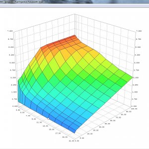
Start of Injection Timing

(click on image to enlarge)
soi_curve_sm.jpg


Keep in mind that these are "DESIRED" values. While SOI and PWM values are consistent between desired and actual, ICP values may vary depending on the capability of the HPOP. It is extremely important to look at the generated values from the datalogs to ensure that the "DESIRED" values and the "ACTUAL" values correlate. In looking at the resulting datalog recorded during the run (below), you can see that not only was the ACTUAL ICP stable and comparable to the DESIRED ICP throughout the run, but even the recorded SOI is right in line with the anticipated SOI from the above graphs.

Datalog - 140x_stage_3_final.xls

Also keep in mind that this is done WITHOUT forcing a maximum SOI Limit like some other tuners do (usually around 35º BTC). This means that this vehicle will run just as well when cold as it does hot. Under normal circumstances, the ECM will advance timing considerably when cold. For example, at 50º F, the SOI Timing curve would look like this...

Start of Injection Timing @ 50º F

(click on image to enlarge)
soi_curve_50_deg_sm.jpg


This is the difference between the two files....

Start of Injection Timing @ 50º F vs. 190º F

(click on image to enlarge)
soi_curve_50_deg_overlay_sm.jpg


The SOI Timing difference is considerable, and clamping the SOI on vehicles that run in colder climates can translate into noticeable cold-start and cold running issues, excessive white smoke, and considerable loss of performance until the engine reaches normal operating temperature. These engines need advanced SOI Timing when cold to offset the low compression temps, cold air charge, cold fuel spray, and even the inherent injection delay cause by the increased viscosity of the cold oil. Obviously, the best approach is to let the PCM handle the SOI in the manner in which it was designed for the best drivability in all situations.

As we've already stated, SOC is not directly related to SOI. This is because the fuel spray relies on the temperature of the compressed air mass in order to ignite. Even a small change in crank angle can have a dramatic effect on the specific temperature of the air mass at the point of injection and can advance or retard the point of combustion. When you take into consideration factors such as block temperature, ambient temperature, aircharge temperature, boost, intercooler efficiency, fuel temperature, injection pressure, spray pattern, atomization, and other minor factors, it becomes a real challenge to identify any sort of SOC point... At least without appropriate CP testing equipment. It is in this that experience has as much to do with tuning as equipment. Historically, there have been a number of ways to approach tuning that vary from the scientific (Dataloggers, CP testers, and other diagnostic equipment) to the downright mystical "experienced tuner's ear". Over the years we've used a combination diagnostic equipment, experience, and just plain old common sense. With nearly 30 years in the automotive performance industry and 15 years in tuning the Ford Power Stroke, we've seen and tuned a wide variety of combinations and have accumulated a wealth of knowledge from every truck we've tuned. We've learned simple tricks to tuning just by using a boost and EGT gauge, and we've developed an ear for adjusting SOI based on the "sound" the engine makes under load. It is this experience that allows people to be able to push beyond normal thinking... To think outside the box and be able to look at a setup and help it to reach its maximum potential. Legends like Smokey Yunick used as much intuition in his approach to racing as he did tools and equipment. There is no question that there is an art to tuning, and some people just seem to "get it" better than others.

Anyway, that about sums up the topic of SOI and SOC. The relationship of Injection PW and ICP is a simple a mater of Fluid Dynamics and can already be easily calculated so there's not much reason for me to elaborate past the point that ICP is derived first and then the Injection PW is determined based on the amount of ICP produced. Pretty straightforward.

I hope this information is helpful. If anyone has any questions, I would be more than happy to answer them for you. Please post them here (do not PM) so that everyone can benefit.
 

CamTom12

Member
Joined
Sep 14, 2011
Messages
821
Reaction score
0
Location
Huntsville, AL
Bill, that's a wonderful write-up. I feel like I have a much more knowlegeable grasp of SOI vs. SOC - which is a huge deal in diesel tuning.

Thanks for sharing your knowlege - I'm sure it'll help the whole diesel community! I wish we had access to an HPTuners/EFI live type tuning platform so I could write a new file to try right now, hahaha.
 

Power Hungry

Member
Joined
Jun 20, 2011
Messages
365
Reaction score
0
Location
Winder, GA
Well, there's always Minotaur. Have a lot of people using it with great success. 907Dave (who is in AK, incidentally), Charles, Blowby (Mike O.), Brian Jelich, and even most of the 7.3L chip tuners use it. :D
 
Last edited:

CamTom12

Member
Joined
Sep 14, 2011
Messages
821
Reaction score
0
Location
Huntsville, AL
Yeah, unfortunately I traded my 7.3 in for my 6.4 about two years ago...

907Dave and I have had a couple of short tuning conversations and I've read a bunch of Charles's posts back on PSN - both definitely know what they're doing.

I've tuned in the gasser world on GMs (HPTuners) and once I understood the tables and how they interrelated it just kind of clicked.

Too bad that kind of thing isn't available for the CR Powerstrokes. I almost want to go buy a dang 7.3 just to try some ideas now though hahaha.
 

Jake P

New member
Joined
May 18, 2011
Messages
160
Reaction score
0
This makes me wanna get into my own tuning even more. One of these day's Bill ill call ya and we can figure something out.

By the way, what is the bottom right side axis on those graphs? I know bottom left is RPM, and vertical is either ICP or PW or whatever the graph is for, but the bottom right, is that like pedal position or something? That would help me make alot more sense of the graphs.
 
Joined
Feb 12, 2012
Messages
655
Reaction score
0
Location
Richmond IL
Thank u bill . I have been using minotaur for a few years now and and i have been happy with it :) . But now if i can only get a hold of u for more definitions .....:poke: . As i understand u are busy and i am grateful that u take the time to share your 15+ years of that brain of your in this tuning market :D. thanks again Bill for post like these as they help me when i don't get time to talk to u on the phone as much i would like .
 

Latest posts

Members online

No members online now.
Top