smokinstroker
New member
Thanks for the answer guys. This is the stuff that helps educate us younger guys that aren't as knowledgable with internals.
Last edited:

Thanks for the answer guys. This is the stuff that helps educate us younger guys that aren't as knowledgable you old guys..

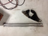
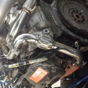
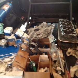
:whs:well i tried my hardest to bend a pushrod the last few days and there all still straight but look what failed and what didnt tonight
Bp is 1:1
Sent from my Droid Charge
Pretty near to that hard to watch all guages at once and edge won't datalog
yeah without bp info, saying 1:1 is pretty vague. maxing out the factory sensor doesnt say anything. huge back pressure is probaly gonna break a rocker arm, or maybe you can blame that on the h-11's !! LOL
on edit: you think the bp was not crazy high spraying it? that alone coulda caused the fatigue and stress, there's prolly more ready to break.
[FONT=Calibri,sans-serif]Just [/FONT][FONT=Calibri,sans-serif]what is valve float?[/FONT]
“Valve float” is a common term for a situation best described as (valve train separation). This occurs due to inertia load imparted into the valve train by the action of the cam lobe against the follower.Weak valve springs are among the most common causes of valve float. Fast lobe profiles, heavy valves, etc force the need for high quality springs with increased pressure. That said, too much pressure can be disastrous to rocker arms and is often unwarranted. Forced induction is another contributor to “valve float”. Because of the increased pressure on the face of the valve, stronger springs are usually warranted.
Flex in the valve train (the majority of which is located in the pushrod) is a prime contributor to valve train separation or “valve float”. The initial loads imparted into the pushrod cause it to bend (somewhat like a pole vaulter’s pole) and then return to a straight configuration. This unloads a sharp energy pulse to the rocker arm, which transfers it into the valve/valve spring assembly. This often results in “valve lofting,” which causes the valve to operate in a different path than that described by the lobe profile. At the same time, the lifter without any load against it, can also be launched off the opening ramp of the lobe and then, as load is re-established, either: strike the nose of the lobe and eventually damage it; land on the closing ramp (like a ski jumper landing on the slope of a hill); or land on the base circle with significant and often damaging impact. If “lofting” can be controlled (by design or good fortune and the lifter lands gently on the closing ramp), it adds to area under the curve and more power. If it is uncontrolled (which happens the vast majority of the time), it can be damaging to valve train components and will compromise performance. Most of the time, power flattens out or is lost when valve train separation occurs. Again, the biggest culprit in causing this situation is the flex of the pushrod.
Many people on website forums tend to think that the “weight” of the rocker arm is the cause of “valve float”. If the rocker is rigid and properly designed, it should contribute very little to “valve float”. Weight in this case is not the prime issue, but rather the “moment of inertia” of the rocker design. “Moment of inertia” is the affect of where the mass of the rocker arm is located relative to its center of rotation. One rocker can be much heavier than another and still have a smaller moment of inertia because of where its mass is located; so weighing rockers to determine their affect of valve float is really not effective at all. (FYI: “mass” is a measure of a body’s inertia; while “weight” is the affect of gravity on “mass.” “Moment of inertia” is unaffected by weight, but is affected by where “mass” is located relative to the center of rotation!). The highest quality aftermarket rocker arms are designed to be rigid (to minimize flex), and have a very low moment of inertia relative to the necessary strength.
Other issues are often misdiagnosed as “valve float”. These issues can mask themselves and give the impression of “valve float”.
11 1. Coil Bind.
Increased lift causes the clearance between the valve spring coils to diminish. The spring can become solid. The minimum recommended clearance is .060”.2.Additional lift can cause the pushrod to travel a different arc. The position of the pushrod in the rocker arm cup and or additional lift can reduce the clearance between the pushrod and the cylinder head. If the pushrod contacts the head during its rotation, it can stall momentarily causing the lifter to expand and pump up, holding the valve open temporarily. The result manifests itself exactly like “valve float”.
3. Proper rocker arm clearance, that is, something interfering with the ability of the rocker to make its full sweep can manifest itself as “valve float”. Clearance should be checked throughout the entire sweep of the rocker arm. The minimum recommended clearance is .60”
Understanding the issues surrounding the phenomenon of valve train separation is paramount in identifying the problem and correcting it. To ensure consistent performance and safety throughout the entire range the engine operates in, valve float must be controlled. Unchecked, valve float can and usually does, contribute to engine destruction.