My tow pig/DD build thread. F350/Cummins 6.7/twins/6R140

me2

New member
Joined
Nov 14, 2011
Messages
548
Reaction score
0
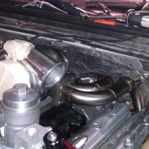
I've decided the easiest way to get a compact, good flowing manifold is to build it up in sections of flat plate, contoured to the various shapes. This is similar to how one manifold manufacturer makes theirs.

Doing this I can get a good manifold, only 3 3/8" wide with flanges, making for an overall HE351 turbo protrusion of 18" from the center of the engine. I'd like to get that down to 17", but 18" is certainly liveable.

Here is what the runners look like in my first CAD attempt. Unfortunately, they will be mostly square in cross section. If I used a CNC mill to make the inserts, I could make them round, but for my purposes I think that I'll use plasma cut sections and thus they will be square except for the welding bead in the corners.

The port area is generally 1.5 x 1.5 inches throughout. The exhaust ports on a 6.7 Cummins are 1.5" round. The exhaust flanges will transition from 1.5" round to 1.5" square.

I'm still debating mild steel versus stainless. I have enough stainless plate to cut these parts, but I'm missing the right thickness for the top and bottom plates. The other issue is that stainless needs shield gas flow on the other side of the weld and its more prone to warping. And its probably more prone to cracking.

I'm debating between 3/16" or 1/4" wall on the manifold, leaning toward 1/4".

manifold1.%2520jpeg.png


The height restrictions under the hood are making for a lot of extra work. The turbo system went from the HE351VE being bolt on to now needing a custom, narrow width manifold.

Its been almost 2 weeks now since I had dedicated time to work on this project. Very frustrating.
 
Last edited:

me2

New member
Joined
Nov 14, 2011
Messages
548
Reaction score
0
Good news.

I found another 2 inches or so of height under the hood.

I've been measuring everything by putting a stick across the fenders when the hood is up and eyeballing things from the top of the fenders.

It turns out that the 08 hood bulges up about 2 inches from the fenderline across most of the engine bay. I totally overlooked that.

I can now probably keep the stock 6.7 valve cover and I can also reposition the turbo a bit, closer to the engine and up a bit.

How much clearance do you think I need between the turbo turbine and the underside of the hood ? WIth or without insulation and/or heat shields ? I don't want to burn the hood paint !

Some turbos seem to be running very close to (plastic) heater boxes with no apparent bad effects. A hood should be pretty durable and forgiving ????

I really wish I had a CAD model for an HE351 turbo. It would make life a lot easier.
 
Last edited:

me2

New member
Joined
Nov 14, 2011
Messages
548
Reaction score
0
Now I'm having tons of problems getting parts cut on a water jet/ laser table.

I'm using the same company that cut my suspension parts 2 years ago. Back then I would email drawings and pickup 6 to 10 pieces the next day for $100.

They have a new guy running things and he doesn't like my drawing files and the quotes I'm getting back are ridiculous. $100 for one plate of the exhaust manifold in 1/4" mild steel and $110 in 3/16" stainless. I need 2 of them to make the manifold. The small difference in material cost between mild and stainless tells me that most of the charge is for labour.

At the prices he is quoting, by the time I do my engine swap, front and rear suspension builds and build an air ride 5th wheel hitch, I'd have a small plasma table mostly paid for. And I already have an 80A plasma cutter that I bought especially for putting on a CNC table some day.

I'll get another quote before I jump the gun and start putting together a small plasma table.
 
Last edited:

Mdub707

Active member
Joined
May 18, 2011
Messages
5,079
Reaction score
0
Location
Mohawk NY
I just stumbled onto this thread this morning. I don't know how I haven't seen this yet. This is awesome. Keep up the great work me2, the details are excellent...

keanu-mind-blown.jpg
 

Rene G

New member
Joined
Dec 3, 2011
Messages
435
Reaction score
0
I just stumbled onto this thread this morning. I don't know how I haven't seen this yet. This is awesome. Keep up the great work me2, the details are excellent...

keanu-mind-blown.jpg

^^WHS^^ this thread is awesome! Your methodical approach to this build is really interesting and informative to follow. Thanks for posting every step of the way.
 

me2

New member
Joined
Nov 14, 2011
Messages
548
Reaction score
0
I'm glad to hear you guys aren't tired of my babbling.

Just for that I'll treat you to a little rant.

I spent the morning resolving the issue of CAD file compatibility with my vendor. Our CAD tools now talk to each other without issue. Yippee.

Total time spent resolving the issue, yesterday and this morning, about 5 hours. I kid you not.

Part of that was spent surveying the available inexpensive CAD software offerings in an effort to change packages. But still !

The real frustrating, time consuming part was finding out, inadvertently, of course, that the DXF R12 format does not support funny shapes, something I used several of in the manifold design. Who knew ? Sheesh !

But the worst part was that the vendor didn't tell me there was anything wrong until I phoned and asked where my parts were. I was thinking they would be ready for running/pickup. Turns out they hadn't even gotten the files open. There goes another 4 days in the swap schedule.

People ask how long it takes to do a swap. There are several answers.

1) It depends on what you are doing.

Twin turbos, obscure transmissions, obscure transmission control regimes, fitting a newish engine into a truck that not many people have swapped into before, all take more time.

2) It depends on your skill level and available knowledge.

Because when you don't know a thing about what you are doing and there aren't others to turn to, there is a bit of a learning curve and figuring out complicated things all by yourself can take a bit of time. At least for me it does.

3) It depends on how much money you want to spend.

If you have enough and you don't care how much it costs, just hire someone to turnkey it for you.

Or, if you have the budget, just turnkey the complicated parts. The flexplate, transmission adapter plate, transmission controller, twin turbo kit and wiring harness come to mind. That greatly simplifies things and speeds things up.

But sometimes it doesn't matter how much money you have because the parts aren't even available, short of hiring someone to do it custom, just for you.

4) It depends on your tool set.

I already semi built an engine stand and upgraded to a new engine hoist with upgraded wheels for this project.

And before that I had to clean out and organize my shop and finish rebuilding the gear box in my band saw.

And prior to that I bought and set up a new TIG and stick box as well as a plasma torch. Not necessarily especially for this project, but because they would be used and needed for this project.

There was a learning curve with each one. Extra stuff had to be bought. Things happened. Remember when I melted my TIG torch down ?

And now I am seriously considering putting together a quick and dirty CNC plasma table.

None of these things are directly "doing an engine swap", but they are all needed to do the engine swap.

5) It depends on how long it takes to get parts (and books and tools, all at a reasonable price).

It took 3 times and 2 months to get the transmission wiring harness for the 6R140. It shouldn't have, but it did. Ditto the Cummins ECM connectors. I could go on, and there are some funny stories, but I'll leave it at that.

Hint, the 5R110 transfer case cannot be made to connect to the 6R140 transmission. Well, it could, but you probably don't want to do it.

You can't put the engine in the truck until everything is purchased, shipped, received, unpacked, inspected, returned for defaults, re ordered, etc. And all that stuff takes time and energy.

6) It depends on how much help you have.

Both on line and in person.

There are some really talented and knowledgeable people out there on the Interwebz and having their input can make or break a project, or at least greatly affect how long it takes to do.

7) It depends on how often you get interrupted.

It takes time to switch back into what you are working on every time you get interrupted, whether that interruption is 15 minutes or 2 weeks, especially when you are working on complicated things.

I get absolutely nothing done in a day if I am working on complicated things and I get interrupted every 15 minutes.


So how long does it take to drop a fully assembled engine and transmission combo into a truck once you have everything together and figured out ? A few weeks working evenings and weekends.

How long does it take to get an engine and transmission combo together and everything sorted out and ready to drop into a truck ? See above.

The 6.7/6R140 into the 08 F350 is an entirely different swap than the 5.9/ZF6 into my '99 F250 was, even though the 5.9 was a CR and I was one of the first ones to do a swap with one. (It took 2 days in my driveway to figure out why it would crank and not start, another day to get the throttle working, another day to get the fuel pressure right to the CP3 and another day to figure out that the clutch was working fine, that it was OK to put the truck in gear ! LOL)

The good part about all this project is that I'm having a ball doing it.

It would be really nice to have my truck running for my holiday next week, but it ain't going to happen. Luckily, or maybe due to good planning, I haven't touched my truck yet and I can still use it.

In the mean time I'll just keep plugging away at the stuff that arises and deal with it the best way I can.

I just cannot wait for the day my 08 is running with twin turbo Cummins power.

As much as I "like" my 08 F350 with the 6.4 and 5R110, having towed with it, I can already see that it won't hold a candle to the twin turbo 6.7/ 6R140 combo.

Rant Over. I feel better now.
 
Last edited:

me2

New member
Joined
Nov 14, 2011
Messages
548
Reaction score
0
Work Arounds

I was relying heavily on getting plate cut by waterjet/laser/plasma cutters for the engine adapter plate pieces, the flexplate adapter and now the exhaust manifold parts.

I did not rely on such services when I did my 5.9CR swap. I built the transmission adapter plate entirely on my own for it.

For those that aren't aware, there are only a few (dowelled) holes on an engine adapter plate that are dimension/location specific.

The dimension/location specific holes that come to mind are the 2 dowel pins on either side of the engine crankshaft on the back of the engine block and the 2 dowel pins on the face of the 6R140.

All the rest of the holes on an adapter plate are loose fitting.

The starter has to be somewhat precisely located, but as long as the teeth engage nicely, its location is fine.

Where I am going with all this is that if I have an issue with getting vendors to cut pieces for a reasonable cost, I have a milling machine equipped with enough XYZ travel and a Digital Read Out (DRO).

I can use it to drill and ream the location/dimension specific holes in plate precisely, drill the loose fitting holes manually and cut the outline of the plates manually with my plasma cutter.

I did it before, I can do it again.

I already spoke to a vendor about cutting the Ford flex plate and that is no problem. As it is heat treated, I want it cut by a waterjet, not a laser or plasma cutter. Its a simple circular cut, it won't cost much.

All this will take extra time on my part and one thing offsetting the cost of getting it done by a vendor is that the 08F350 uses about 50% more fuel pulling the trailer than the 5.9 did in my '99. I have to give this all some thought.

I know that some of what I am talking about doesn't make much sense without pictures. I'll get some so that people can see what I am talking about.

I knew this winter when I was preparing for the swap that a CNC plasma cutter would be very handy to have. I should have put a small one together back then.
 
Last edited:

me2

New member
Joined
Nov 14, 2011
Messages
548
Reaction score
0
The worst part about not knowing what you are doing is when a critical decision snowballs.

For example, on this project I assumed that I could put a turbo above the exhaust manifold. I assumed that because I saw pictures of another 6.7 (outside of the truck) where it was done. I assumed that worked.

It turns out that the owner of that truck hasn't installed the engine yet and I'm guessing it is not going to fit with the turbo mounted like that.

When I measured things and found it probably wouldn't fit in my truck and I found I had height issues, it precipitated a whole bunch of things, including now having to build a manifold to get a good turbo position. Those sorts of things really throw schedules out of whack.

The flexplate has been a pain too, but I knew I didn't know anything about it when I started this thread. So it hasn't been any worse than I thought it would be.

The CAN Bus stuff is complicated too, but I knew I didn't know anything about it and I got ahead of it learning wise and now I THINK I know what I am doing with it. But I haven't actually run anything with it yet, so we'll see.

Shifting the 6R140 is going to be a lot of fun. I have absolutely no idea how that is going to work out ! LOL And I am not kidding either !

The fun continues.

BTW, of course there are easier ways to swap a 6.7 into a Superduty. I'm a glutton for punishment and I like the challenge. And I think I'll like the end result.
 
Last edited:

me2

New member
Joined
Nov 14, 2011
Messages
548
Reaction score
0
Here is a performance graph of twin versus single turbocharger compressor setups that I wanted to use about 15 pages ago to explain why I was going with twins rather than a big single.

I'm not trying to start a discussion or get off track. I just came across the graph and thought I'd post it while I had it to complete the discussion.

BDdieselcompressormap.jpg


Multiply Kg/sec by 132 to get lbs per minute.
0.8 Kg/sec = 105 pounds per minute.
0.6 Kg/sec = 79 pounds per minute.

600 HP needs a good (ie not hot) 80 pounds per minute (0.6 Kg/sec) for reasonable EGTs.

A PR of 4 is about 40 pounds of boost by the time air filter and intercooler restrictions are taken into account. PR of 6 is about 70 PSI.

The Towing Twins and R700 use the Super B as the secondary turbo. Notice how much more pressure and the increase in flow that the twins setup achieves versus the Super B alone.

The R850 uses the Super B Special as the secondary turbo. Notice how much better the R850 Twin setup does at LOW FLOWS compared to the Super B Special alone. This is because both the primary and secondary turbos are creating boost and their compounded boost is better than the boost that could be produced by the Super B Special by itself.

At 0.3 Kg/sec, the Super B Special will push a PR of 3.5, which is 36.75 PSI under perfect conditions, less in the real world. The R850 twin setup achieves a PR of 4.5, which is 50 PSI in perfect conditions. The R850 achieves better low flow performance than either turbo could achieve on its own, because even at that low flow, the boost is compounding.

A Cummins 6.7 making 1200 ftlbs at 1600 RPM needs 52 pounds of air per minute (0.4 Kg/sec) to stay cool. It takes over 50 PSI of boost to do that, which requires a PR of at least 4 in the real world to achieve.

The Super B Special by itself will achieve that boost, but it runs out of pressure and is at the edge of its map before it hits the 0.6 Kg/sec to make 600 HP on the top end.

The R750 and the R850 setups will easily achieve both the low end boost requirements (PR > 4 @ 0.4 Kg/sec) and the high end (flow > 0.6 Kg/sec). The Towing Twins achieves the 0.6 Kg/sec flow rate, but only just.

The Super B is a 57mm turbocharger. I don't know what the Super B Special is.

The Towing Twins use an S366 with the Super B as the secondary. So the compressors are about 66 and 57.

The R750 uses an S471 and the Super B. So the compressors about about 71 and 57.

The R850 uses an S475 and the Super B Special. I'm guessing the compressors are 75 and 60ish.

I'm using an S475 and the HE351VGT, which has a 60 mm compressor. I expect my twin setup will perform somewhere between the RS750 and the RS850, hopefully with the good parts of each.

The benchmarks for my turbo setup is 50PSI of boost at 1600RPM, 50 PSI of boost at 2700 RPM and no surging anywhere and cool EGTs everywhere.

Of course none of this matters unless its on an engine installed in a truck. Back to the issues at hand.

Edit. In case anyone is interested, a PR of 9 is 117 PSI under perfect conditions, probably 100 PSI in the real world.
 
Last edited:

me2

New member
Joined
Nov 14, 2011
Messages
548
Reaction score
0
I've given up on getting parts cut by someone else for a reasonable cost. I'm not going to spend $60 to $110 for every piece I need cut, especially when they are as small and trivial as the parts I need.

I am thus going to build a CNC plasma cutter and cut my own parts. I am sure it will get a ton of use and save me money in the long run.

I hope to get a design for the CNC table together today and order the necessary parts before the weekend.

While waiting for the parts to arrive, I am going to tear apart my engine and do the rods, frost plugs, etc.

When the CNC parts come back I'll put together the table and then resume making the engine adapter plate and the exhaust manifold.

Theoretically I could hand cut the adapter plate and exhaust manifold parts. I am very tempted to do that but a) I know that sooner or later I need a CNC plasma cutter and b) the quality of my hand cut parts would never match what a CNC cutter will do.

I am off to research DIY CNC plasma cutters.
 

me2

New member
Joined
Nov 14, 2011
Messages
548
Reaction score
0
3) It depends on how much money you want to spend.

If you have enough and you don't care how much it costs, just hire someone to turnkey it for you.

Or, if you have the budget, just turnkey the complicated parts. The flexplate, transmission adapter plate, transmission controller, twin turbo kit and wiring harness come to mind. That greatly simplifies things and speeds things up.

Except when it doesn't. Sometimes buying parts doesn't mean they are going to work for you.

Project20V is having a number of problems in this respect. I'm not picking on him, I think he is doing a great job. He is going to have a really nice truck when he is done.

I'm just trying to illustrate that when you start buying parts for a very specific application, sometimes things don't go as planned.

In another forum he writes this.

I now have 3 new issues:

The adapter plate hits the Haisley plate. I will need to cut, grind or mill a section of the adapter to clear the Haisley plate.

The exhaust elbow interferes with the adapter plate. I may have to remove the elbow and build a downpipe that couples direct to the turbo or modify the adapter plate in this area as well. I'm not sure yet.

The Glacier wastegate tube will contact the starter. I will need to shorten and reroute the exh. tube.

He is having these problems because none of the parts that he bought were intended to be used the way he is using them.

The Hainsley plate blocks off one of the frost plugs on the back of the 6.7 block. It is designed to be used on Dodge trucks with Dodge transmissions. ProjectV20 is using a ZF6 transmission from a 6.4.

The 6.4 ZF6 bellhousing is larger than the Dodge transmission bellhousings, thus the 6.4 ZF6 transmission adapter plate interferes with the Hainsley plate on the back of the block.

His stock 6.7 HE351VE exhaust elbow also won't clear the 6.4 ZF6 adapter plate either. Also because the 6.4 ZF6 adapter plate is larger than the standard Dodge transmission adapter plate.

And the wastegate blow off valve that he got that goes between the stock Cummins 6.7 exhaust manifold and into the downpipe interferes with the starter which is now on the passenger side because that is where Ford puts it on the 6.4s and thus that is where the cut out is for it in the ZF6 transmission bellhousing. Dodge puts the starter on the driver's side.

So just because ProjectV20 bought off the shelf parts doesn't mean their use is problem free. This is the nature of doing a swap. Nothing is really turnkey and you have to be prepared to solve the problems that arise.

ProjectV20's last 2 issues demonstrate why I did not go ahead and build my twins piping and exhaust manifold UNTIL I had the engine adapter done and on the engine. The engine adapter dictates too many things concerning where turbos and pipes can go to do any work on that stuff until the adapter is complete. It seems like a waste of time not to be putting the manifold and twins piping together, but sometimes haste makes waste and doing things in their logical order actually saves time.

ProjectV20 didn't mention it in his list, but the stock Dodge downpipe that he bought hoping to use isn't going to work either.

Now just because these parts don't work directly doesn't mean it was a waste to buy them. In most cases its probably easier to modify parts you purchase rather than build parts from scratch.

And, in defense of ProjectV20, I'm not sure I would have foreseen the issues he is having with these parts either. After all, a few pages back I thought the Cummins marine valve cover was going to be a bolt on for my engine and HE pointed out that it wasn't. a) Everyone overlooks things from time to time and b) its great having other people watch what you are doing.

I hope this stuff doesn't scare people off from doing a swap. All these problems are surmountable. It just takes a bit of extra time and effort. As long as you allocate enough time and energy to a swap, you will not be disappointed in how it goes.
 
Last edited:

me2

New member
Joined
Nov 14, 2011
Messages
548
Reaction score
0
How on earth are you going to make 50psi at 1600?
Rather than argue and debate that, why don't we just wait and see if I can. After all, it doesn't matter what we determine on here, what matters is what the engine does in the truck.

I promise to report exactly what it does, good or bad when I get it running. There will be dyno runs, and not the 10 second variety either.

The really short answer is that a Cummins 6.7 flows 40+ pounds per hour at 1600 RPM and 50 PSI and the required pressure ratios to achieve that are well within the maps of the turbos I chose, both on the turbine side and on the compressor side.

And I'll have EFI Live to help me tune engine timing, fuel delivery and the VGT operation on the HE351.

So THEORETICALLY, it should be achievable.

Like everything else about this project, stay tuned to see how it really turns out.
 
Last edited:

Project20v

New member
Joined
May 29, 2012
Messages
57
Reaction score
0
Location
Eatonville, WA

Lol, you can throw all the theoretical physics and math you want at it, but 6.7 liters will not create enough exhaust energy to make 50psi at 1600rpm. That much energy from 6.7 liters is going to occur at a higher rpm. I'm not trying to be a downer and this is just my un-scientific OPINION.

Great things are accomplished with ambition, having a goal and working towards it is the way to get it done. Good luck I will certainley stay tuned.
 

rusty1161

Member
Joined
Jun 21, 2011
Messages
876
Reaction score
0
Location
Whittier, CA
I'm glad to hear you guys aren't tired of my babbling.

Just for that I'll treat you to a little rant.

I spent the morning resolving the issue of CAD file compatibility with my vendor. Our CAD tools now talk to each other without issue. Yippee.

Total time spent resolving the issue, yesterday and this morning, about 5 hours. I kid you not.

Part of that was spent surveying the available inexpensive CAD software offerings in an effort to change packages. But still !

The real frustrating, time consuming part was finding out, inadvertently, of course, that the DXF R12 format does not support funny shapes, something I used several of in the manifold design. Who knew ? Sheesh !

But the worst part was that the vendor didn't tell me there was anything wrong until I phoned and asked where my parts were. I was thinking they would be ready for running/pickup. Turns out they hadn't even gotten the files open. There goes another 4 days in the swap schedule.

People ask how long it takes to do a swap. There are several answers.

1) It depends on what you are doing.

Twin turbos, obscure transmissions, obscure transmission control regimes, fitting a newish engine into a truck that not many people have swapped into before, all take more time.

2) It depends on your skill level and available knowledge.

Because when you don't know a thing about what you are doing and there aren't others to turn to, there is a bit of a learning curve and figuring out complicated things all by yourself can take a bit of time. At least for me it does.

3) It depends on how much money you want to spend.

If you have enough and you don't care how much it costs, just hire someone to turnkey it for you.

Or, if you have the budget, just turnkey the complicated parts. The flexplate, transmission adapter plate, transmission controller, twin turbo kit and wiring harness come to mind. That greatly simplifies things and speeds things up.

But sometimes it doesn't matter how much money you have because the parts aren't even available, short of hiring someone to do it custom, just for you.

4) It depends on your tool set.

I already semi built an engine stand and upgraded to a new engine hoist with upgraded wheels for this project.

And before that I had to clean out and organize my shop and finish rebuilding the gear box in my band saw.

And prior to that I bought and set up a new TIG and stick box as well as a plasma torch. Not necessarily especially for this project, but because they would be used and needed for this project.

There was a learning curve with each one. Extra stuff had to be bought. Things happened. Remember when I melted my TIG torch down ?

And now I am seriously considering putting together a quick and dirty CNC plasma table.

None of these things are directly "doing an engine swap", but they are all needed to do the engine swap.

5) It depends on how long it takes to get parts (and books and tools, all at a reasonable price).

It took 3 times and 2 months to get the transmission wiring harness for the 6R140. It shouldn't have, but it did. Ditto the Cummins ECM connectors. I could go on, and there are some funny stories, but I'll leave it at that.

Hint, the 5R110 transfer case cannot be made to connect to the 6R140 transmission. Well, it could, but you probably don't want to do it.

You can't put the engine in the truck until everything is purchased, shipped, received, unpacked, inspected, returned for defaults, re ordered, etc. And all that stuff takes time and energy.

6) It depends on how much help you have.

Both on line and in person.

There are some really talented and knowledgeable people out there on the Interwebz and having their input can make or break a project, or at least greatly affect how long it takes to do.

7) It depends on how often you get interrupted.

It takes time to switch back into what you are working on every time you get interrupted, whether that interruption is 15 minutes or 2 weeks, especially when you are working on complicated things.

I get absolutely nothing done in a day if I am working on complicated things and I get interrupted every 15 minutes.


So how long does it take to drop a fully assembled engine and transmission combo into a truck once you have everything together and figured out ? A few weeks working evenings and weekends.

How long does it take to get an engine and transmission combo together and everything sorted out and ready to drop into a truck ? See above.

The 6.7/6R140 into the 08 F350 is an entirely different swap than the 5.9/ZF6 into my '99 F250 was, even though the 5.9 was a CR and I was one of the first ones to do a swap with one. (It took 2 days in my driveway to figure out why it would crank and not start, another day to get the throttle working, another day to get the fuel pressure right to the CP3 and another day to figure out that the clutch was working fine, that it was OK to put the truck in gear ! LOL)

The good part about all this project is that I'm having a ball doing it.

It would be really nice to have my truck running for my holiday next week, but it ain't going to happen. Luckily, or maybe due to good planning, I haven't touched my truck yet and I can still use it.

In the mean time I'll just keep plugging away at the stuff that arises and deal with it the best way I can.

I just cannot wait for the day my 08 is running with twin turbo Cummins power.

As much as I "like" my 08 F350 with the 6.4 and 5R110, having towed with it, I can already see that it won't hold a candle to the twin turbo 6.7/ 6R140 combo.

Rant Over. I feel better now.

You have a very supportive boss(wife)!!!!!

Awesome project!!

Rusty
 

me2

New member
Joined
Nov 14, 2011
Messages
548
Reaction score
0
You have a very supportive boss(wife)!!!!!

Awesome project!!

Rusty

Thanks.

Its easier to get buy in for a project like this when you consider that a new F350 costs twice what I paid for my 08 and other than time this swap isn't going to cost a whole lot.

Lets not forget that I still have my '99 F250 (13 years now) and its still in good condition. I spent very little on it over the years and thus spending some time and money on my 08 in anticipation of keeping for a long time like the '99 doesn't seem so bad.
 
Last edited:

me2

New member
Joined
Nov 14, 2011
Messages
548
Reaction score
0
So, the CNC stuff is taking up a lot of time. Check the thread for a minimal update if you are interested.

I'm !&^%$* that the CNC stuff has become a project within this project and totally derailed things. I keep telling myself that in the long run its a good thing. Seems like it takes a project to make me update tools and equipment sometimes. Maybe I should learn from that and update my tools BEFORE I start a new project that might need them.

Anyway... the Cummins 24V marine valve cover arrived. Part number 3969481 for the cover, $180, part number 3973511 for the filler cap, $6.

DSC_7476.jpg


As previously discussed, and as I knew before I ordered it, the cover is not a direct fit on a 6.7.

Shape wise, it fits pretty much perfectly on the exhaust side.

DSC_7458.jpg


Shape wise, it fits just about perfect on the back.

DSC_7459.jpg


Shape wise, it fits perfectly in the front.

DSC_7460.jpg


Shape wise, where it doesn't fit well is on the intake side, where the injectors are. On the 24V and 5.9CRs, the valve cover cuts in where the injectors are. On the 6.7, it doesn't have to, so it doesn't. The side is straight.

DSC_7478.jpg


Here are the two valve covers sitting upside down, side by side. Stock 6.7 on the left, 24V marine on the right. The intake side of the valve cover is on the right of each. The 6.7 valve cover is straight and the 24V marine cover has the cut ins.

Here is a (bad) view of the 24V marine cover on the 6.7. Not how the gasket is straight and the marine cover has cut ins.

DSC_7461.jpg


Luckily the "rocker lever housing", what Cummins calls the aluminum piece that goes between head and the valve cover, does not appear to have anything in the way to prevent the marine valve cover from closing.

The 6.7 valve cover gasket, however, does prevent the marine valve cover from closing.

DSC_7463.jpg


The cut ins on the marine valve cover sit directly over a boss that is part of the rocker lever housing. There is no issue with them. However, the connector for the injector wiring harness sits over the bosses in 2 locations and prevents the cover from fully coming to rest on the rest of the gasket.

Actually, its not even the connector that is the problem, it is the plastic arm that sits next to the connector that holds the wires and prevents them from contacting a rocker arm.

DSC_7475.jpg


The other issue is the sealing lip. The marine valve cover has a groove cut in the bottom of it all the way around. The 6.7 valve cover has a flat bottom.

DSC_7480.jpg


There are a couple ways to make the cover fit.

1) Trim the wiring harness and weld aluminum extension plates between the cut ins on the marine cover so that it has a straight sealing surface on the intake side.

2) Replace the 6.7 injector harness/valve cover gasket with a 5.9 valve cover gasket ($200) that fits the 6.7 wiring harness and then build up the bosses on the rocker lever housing so that they are flat and thus the marine valve cover could seal to them.

3) Replace the 6.7 rocker lever housing (about $200) and the valve cover gasket (about $110) with parts that work with the marine cover. I believe that some of the later 5.9CRs have a valve cover gasket that will work with the 08 wiring harness, ditto for the rocker lever housing.

The other issue is that the marine valve cover is a bit taller than the 6.7 valve cover. This will allow it to be milled smooth to work with the 6.7 style valve cover gasked if needed.

I keep thinking that a similar marine valve cover should exist for the 6.7. But I've yet to find one.

I have not yet decided how I am going to resolve the valve cover fit issue.
 

Project20v

New member
Joined
May 29, 2012
Messages
57
Reaction score
0
Location
Eatonville, WA
That cover looks nice, but I don't think you are going to "need" it. I have my engine/trans. placement final, well almost and the height is not an issue. I have 1" clearance to the sound dampening material under the hood and that deflects another inch and a half or so. The only issue now is the turbo is touching the HVAC.
 

Latest posts

Members online

Top