My tow pig/DD build thread. F350/Cummins 6.7/twins/6R140

me2

New member
Joined
Nov 14, 2011
Messages
548
Reaction score
0
I'm finally back home, after 8 days. I put another 1500 miles on my 08. I guess that is what I bought it for. Its a great truck.

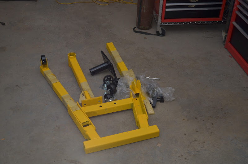
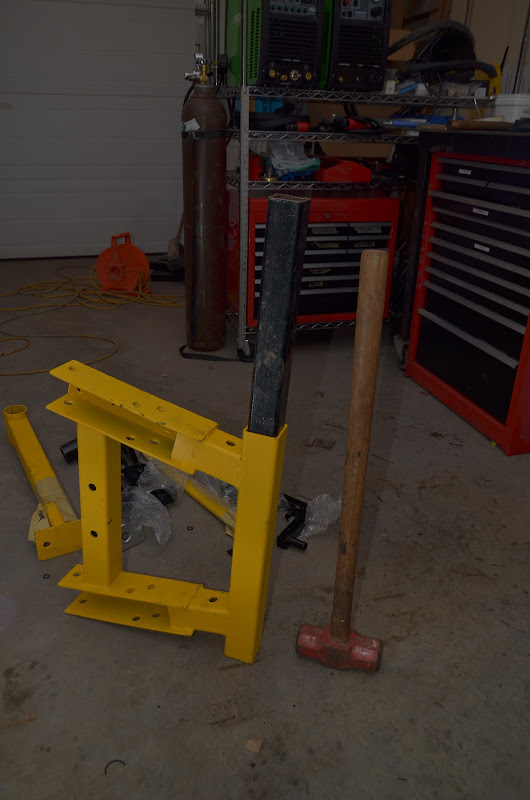
I'm now about a week behind where I thought I'd be on this project. I hope to be back in the shop finishing up the engine stand later today. After that the engine gets stripped so that I can install the rods block. I need to pull a piston pin ASAP in order for the machine shop to fit the new rod bushings.

Turbos

Warning. You are about to enter the boring zone.

I'm looking for 600 HP. Actually what I am really looking for is an engine
with 1000 to 1200 ftlbs of torque, between 1600 and 2600+ RPM, and that just happens to be 600 HP.

1200 ftlbs @ 2750 RPM = 628 HP.
1200 ftlbs @ 1600 RPM = 365 HP, which is more than my 5.9CR makes at 3,000 RPM !

Anyway, I'm looking for a broad, torquey powerband. 1600 to 2600RPM+.

Lets put some numbers to this.

Fuel consumption (lbs/hr) = power x BSFC.

600 HP x 0.4 lbs/HP Hr = 240 pound of fuel per hour

What is BSFC ? http://www.google.ca/url?sa=t&rct=j...TeRwGf7NpGPig34kA&sig2=yd6qYqYyxzwPtVIxvHk6gg

Where did I get 0.4 lbs/HP HR from ? a) Its a bit of a wild a$$ guess. b) I have a Cummins Competitive Engine handbook from back in the 80s and c) I calculated it from my 6.7 dataplate and then added a fudge factor.

Here is the data plate from my 6.7

20120522_002.jpg


It says my 6.7 outputs 350 HP at 3013 RPM with 132 mm^3 injections.

3013 *6 /2 * 132 *60 = 71.6 liters per hour

/ 3.78 l/gallon * 7 pounds per gallon = 132.6 pounds per hour.

132.6 / 350 = 0.379 lbs/ HP Hr

Lets not forget that is with EGR operating and DPF injections occuring.

I used 0.4 lbs per HP HR for easy calculation. In reality, there are a whole host of factors at play here, including timing, having enough air to burn the fuel, etc. 0.4 might not be exactly right, but if the engine isn't smoking and the EGTs are within reason, its probably not that far out.

So lets assume a BSFC of 0.4. If that is true, my engine will consume 240 pounds of fuel an hour. Diesel weighs 7 pounds per gallon, so that is 34 GPH. If the engine needed all 600 HP to pull the trailer at 68 MPH, the truck would get 2 MPG.

A diesel engine needs an air fuel ratio of about 19:1 to burn cleanly and keep EGTs under control. Lets assume an AFR of 20:1. Google "diesel air fuel ratio" if you have questions about this.

240 pounds of fuel per hour x 20 lbs of air per pound of fuel = 4800 pounds of air per hour.

4800 lbs per hour /60 = 80 pounds per minute.

So my 600 HP engine is going to need about 80 pounds of air a minute to run cleanly and cool.

The stock HE351VE is maxed out at about 50 pounds per hour.

An HE451VE, which I have on the shelf, will supply 80 pounds per hour, but
a) its on the edge of its compressor map and b) it doesn't have enough pressure, which I'll get to in a bit.

After a bunch of looking around, I selected a BW S475, specifically, part number 171702. They are available for sale new for less than $800.

Here is its compressor map.
S475%2520map.jpg


Its in the meat of its map at 80 lbs/min, which is what I want.

When turbos get to the edge of their map, their efficiency drops, meaning the air they produce is very hot. I want a turbo setup that is loafing, not one that is straining.

Butt check. This turbo is standard issue on Detroit Diesel Series 60 14 liter engines, rated at 550 HP.

So why do I need twin turbo chargers ?

Lets back up.

What I am basically trying to do is get big bore diesel power out of a 6.7 liter engine. To do that, I need to get as much air into my 6.7 as what goes into a big bore engine.

DD S60 airflow.

Air flow for a 14L S60 turning 2,000 RPM at 30 pounds of boost is

14 L x 2,000 RPM/2 x PR of 3 = 42,000 litres per minute.

PR = pressure ratio. A PR of 3 is about 30 pounds of boost.

To get the same air flow through my 6.7, I need more RPMs and a higher PR.

6.7 L x 3,000 RPM/2 x PR of 4.5 = about 45,000 liters per minute.

Same air flow. Same power potential. Different torque, because one is reving 2,000 RPM and the other is reving at 3,000 RPM.

A PR of 4.5 = 52.5 PSI of boost.

If you look at the S475 compressor map, it will deliver air at a PR of 4.5 only in the upper portion of its map and even then its straining. It will surge at that pressure at lower flow rates (RPMs).

My engine needs 1200 ftlbs across as much of the powerband as possible.

Since the S60 flows twice as much air as the 6.7 everywhere, but my 6.7 is turning only about 50% more RPM everywhere, the 6.7 needs an extra 50% boost everywhere as well to get the same air flow. That means my turbo setup must be capable of delivering 40+ PSI of boost everywhere across the powerband, preferably a full 52.5 PSI. As far as I know, a compound turbo setup is the only way to accomplish this.

I'm not pretending that my 6.7 is any sort of a substitute for a DD S60. It should make the same power as one, intermitently, but that is where the simularities end. The Cummins 6.7 XT ISB is rated for a 33K GCWR in RVs.

Both the HE351VE and the S475 will be loafing in a compound setup at 50 PSI, though things will be interesting down at 1600 RPM.

Turbo Setup

When I came to the conclusion that I needed twin turbochargers to achieve the air flow for the power and torque I was shooting for, the question became "how ?".

Being on a budget and wanting to keep things simple, and wanting to retain the exhaust brake, I'll be using the stock HE351VE turbocharger on the stock manifold in the stock location as the secondary charger.

I'll be mounting the S475 on top of the stock turbocharger as the primary.

I will not be waste gating the HE351VE, at least not initially. I want to see how it does in a compound setup first.

I'll be fabbing up the hot and cold pipes for this setup before the engine goes into the truck.

A lot of people on diesel sites already know this turbo stuff. I didn't, so I wrote it up. I hope I didn't bore anyone to death. I'll get back to actually building things shortly.

As far as the EFI Live side of things goes, I'll comment on that once I start tuning the engine, after its running in the truck with stock power.

Stay tuned.
 
Last edited:

me2

New member
Joined
Nov 14, 2011
Messages
548
Reaction score
0
It turns out that if I am going to replace the rods in my engine, I need a real engine stand.

Had I not chosen to replace the rods, I would have worked on the engine while it was sitting in a wooden cradle, similar to this. That is what I did with my first swap.

DSC_6868.jpg


The cradle is something I threw together with some scrap wood. The blocking holds the engine up on the pan bolts. The engine isn't at the right height, but providing you don't have to do anything to the pan, it works.

However, when one changes the rods, the pan must be removed so that one can get to the rod caps. Theoretically one could do this with the engine hanging from a shop hoist, but I don't think that is a very safe or convenient way to do it.

So the search began for an engine stand.

Its difficult to find a stand for the Cummins 5.9/6.7 engines because most stands are built for a typical V8 engine and the 5.9/6.7s are way longer and heavier than a typical V8 engine.

I spoke with several people who had worked on a 5.9/6.7 on a stand. The general consensous was that all but the heaviest automotive stands were downright dangerous and only the largest automotive type stands, with reinforcing straps on the main post, were suitable for working on a Cummins.

With this in mind and a little more research, I settled on wanting a stand like this one.
http://www.northerntool.com/shop/tools/product_200485241_200485241

However, none of the retailers in my area had such a stand. After a while I located a stand very similar to that one, albeit without the tool tray and the screw down feet. However, the one I got folds up for storage, something that is very important to me because my shop is tiny.

I paid $100 for it because its missing a few pieces and the paint job isn't up to snuff.

DSC_6869.JPG


There isn't much to these stands. I was honestly going to build my own from scratch, but couldn't justify the effort for the few hours I am going to need it for this build.

Having looked at several high end commercial stands while doing all this, there was no way I am going to leave the stand as I bought it.

For starters, I am not going to mount my engine on the stand at the back of the block. A large part of my work on my engine involves building the adapter plate. I thus need access to the flywheel end of the engine and thus I'll be mounting my engine from the side using the engine mount bolts. I'm not alone in doing this. I've seen 2 engine build threads where others did this as well.

The next thing that needs to be addressed is the stability of the stand. The footprint on my stand was 36x36. Judging by the size of the commercial ($5K) stands, that isn't large enough. So I increasee the width of the platform wheels by driving 2x2x1/4 wall square tubing into the existing wheel mount tube. This increases the rear width from 20 inches (!) to 48 inches.

DSC_6877.JPG


I'll be adding an extension to the front legs as well, so that the overall footprint is 48x48. That should greatly increase the stability.

Another thing I got from talking to people is that these engines are pretty hard to rotate.

Ideally, one would be using a stand like this one, with a higher weight rating and a larger footprint.
http://www.northerntool.com/shop/tools/product_200349940_200349940

To make mine easier to rotate, I'll be making my mount assembly so that the center of rotation is closer to the center of the block. And I'll be using a long pipe to help rotate the engine.
DSC_6881.jpg


I'm also mounting larger wheels on the stand so that it rolls better. I find engine hoists and engine stands to be very prone to tipping over because their wheels are too small, they roll hard and they skid on any little bit of debris, making them prone to trip up the stand itself.

Another thing I had to check was that I could load the engine onto the stand using the (new) shop crane. It looks trivial in this picture, but it won't be once the legs are extended and connected together.
DSC_6885.jpg


I hope to have the stand done tomorrow, so that I can I tear the engine apart on the weekend.

In other news, the Ford harness for the transmission finally arrived. It took several tries to get it. It should have been trivial, but it wasn't.

I had no such luck with the hot pipe materials, however. The outlet flange for the HE351VE did not fit. Another one has been ordered.
 
Last edited:

me2

New member
Joined
Nov 14, 2011
Messages
548
Reaction score
0
600/1200 sounds awesome, but in my opinion it is too much strain for 6.7 liters to be durable and reliable.
Fair enough. You might be entirely correct. We'll find out.

Cummins ships the 6.7 as the ISB-XT rated at 360/800 at a governed speed of 2600 RPM for use in 20,000 pound motorhomes operating to a GCWR of 33K. Cummins warranties the engine in this application for 100,000 miles, with optional coverage to much more.

http://cumminsengines.com/every/applications/motorhome/EPA_2010_ISB67_MH.page?

The ISB-XT is doing that with the 20% EGR, DPF, a stock HE351VE and cracked cap connecting rods. With a 15,000 mile/500 hour oil change interval at 20K pounds, though the XT does have a larger oil pan than the Dodge ISB.

My engine will be deleted, twin turbod and has 24V machined split connecting rods.

80% of the time it will be pushing an 8500 pound pickup truck and the other 20% of the time it will be loaded to a GCWR of about 22K.

Will my 6.7 take that kind of punishment ? We'll find out.

Back to the task at hand.
 
Last edited:

me2

New member
Joined
Nov 14, 2011
Messages
548
Reaction score
0
Thanks for the supportive comments.

I started the day cutting and drilling various mounting plates.

DSC_6889.jpg


I then lengthend the legs.

DSC_6891.jpg


I cut the new cross member.

DSC_6892.jpg


BTW, that is the saw that I replaced the gear box bearing in. It works great again. My family bought it in 1988. Its cut a bit of steel since then !

Then I started welding things together.

DSC_6904.JPG


This is what I am welding with these days. For those not familiar, its an Everlast PP256. (TIG, stick, plasma.) It works great. I'll talk about it more another time.

Next to it is an Everlast Power Plasma 80. I haven't used it yet because I haven't plumbed in the air tank and dryer. But I did buy all the fittings to do so yesterday. I hope to use it tomorrow

DSC_6901.jpg


A bit more drilling. I know my mill is disgustingly dirty.

DSC_6919.jpg


A bit of bolting. And we have an assembled engine stand.

DSC_6925.jpg


DSC_6927.jpg


The base is now 48 x 48. You can see how big the old base was by where the yellow steel ends. That is where the wheels would have mounted, front and back.

The wheels are 4 inch and roll nicely. They are rated for 450 pounds each.

I might have to raise the center post yet. I'm also not happy with the angle it sits at. I think its useable for now.

The stand still folds up. To do so, one unbolts the front cross member and sets it aside and then pulls the pins on the front legs. They then fold up beside the center post.

I have about $200 in this stand now. As far as I know, its more stable than all the other stands out there, except for the $7500 OTC model.

I know its going to be a pain stepping (tripping) over the front bar all the time. I might put a bit of a platform on the front to make it better. I'll see how it is when I use it.

When I was rebuilding things, I thought about not using the front bar and widening the stance of the legs and making them go straight out. I think it would have taken a lot more fabricating to make that work and be as strong and still fold.

I know I said that I would only be using it for my 6.7. But that isn't entirely true. I am probably going to do the rods and head gasket in my 5.9 and I'll probably rebuild my 5R110 too, so this won't be the last project I'll be using it for.

Anyway, its done.

Tomorrow I'll start on the engine mount for the 6.7. As soon as that is done, I'll start tearing down my 6.7.

In other news, I got a bunch of parts from Cummins today. And they are all parts that I want, versus what I got last time I ordered. I'll post that up with prices, pictures and part numbers some day when I am bored and not working in the shop.

Edit. It feels great to (finally) be working on something. Its been a long journey to get to this point.

I'm a bit peaved that this project isn't done already. I bought the truck and engine in November. I was hoping to do it in April, but it took way longer to figure things out and get various bits and pieces to even start the project. Its only in the last couple weeks that everything started coming together such that I knew it was doable.

BTW, I picked the engine up the day after I bought the truck. The swap was planned as part of the purchase. Although I certainly didn't have the transmission selected or figured out. That didn't happen until late January and is a major reason why things are behind schedule.

20111026_002.jpg
 
Last edited:

me2

New member
Joined
Nov 14, 2011
Messages
548
Reaction score
0
I started on the engine mount for the engine stand.

I'm building this mount so that the engine can be mounted from the side, so it more stable and so that I have access to the flywheel to work on the adapter plate and flexplate.

DSC_6930.jpg


DSC_6932.jpg


The extra pieces are the wheel mounting plates that go on the engine hoist. One of the new wheels is visible in the upper right hand corner.

DSC_6939.jpg


This is what it will look like when its done.
DSC_6934.jpg


The engine stand and engine stand mount just need a couple hours of welding to be ready to use.

The reason for changing the wheels on the engine hoist were that a) it will roll better, especially when there is debris on the floor, b) with the mounts the engine hoist legs fit under the engine stand so that I don't have to take it apart to pickup or drop off the engine and c) with the new mounts it increases the stance of the engine hoist a bit. About 16" in the back and 6 inches longer and 4 inches wider in the front.

As you can probably tell, I'm kind of paranoid and fed up with using engine hoists that don't roll well and constantly want to tip over.
 
Last edited:

me2

New member
Joined
Nov 14, 2011
Messages
548
Reaction score
0
Cummins 6.7 ECMs.

Caveat. I am not an expert on this topic. I'm only sharing what I have learned.

Dates

When talking about ECM dates, there are at least 4 dates to be aware of. Maybe 5.

Engine Build Date. This is the date Cummins built the engine. Not generally used, but once in a while a partsman will ask for it. This date is on the engine.

Engine Warranty Date. This date is viewable in Quickserve. I suspect that Chrysler tells Cummins when the truck is sold and they tag this date as that for warranty purposes.

Truck Build Date. This is the date that Dodge built the truck. Note that the engine build date and the truck build date are not the same. The Dodge partsman wants the truck build date, but the Cummins partsman sometimes wants the engine build date. A Dodge parts man can give you the truck build date from the truck VIN. If he wants to.

Wreckers like to use truck build date.

Truck Model Year. I don't know how to explain this, but you guys know what I mean by it. An 08 MY truck generally starts selling in mid to late 07.

All these dates are different and when someone starts throwing around a date, you need to know which one they are referencing. Dodge and Cummins generally get around this issue by using VIN and Engine Serial Number (ESN) respectively, but there are exceptions and everyone else has their own system.

So when someone says they have an 08 6.7, it could mean
Cummins built it in 08.
It came from a Dodge truck that was built in 08.
It came from a 08 model year Dodge truck.
It shipped to the customer in 08.

There is one other applicable date, that being the emissions certification date.

6.7 ECMs.

Thus far there are two versions of the Dodge 6.7 engine.

The first was is commonly referred to as the 07.5 to 09.5. When people say this, they are referring to MY. The second version is commonly referred to as 09.5+ or 09.5-11.

I know of the following major differences between the two engines.

1) The later engines use different rods. Still cracked cap though.
2) The later engines use a different ECM
3) The later engines use different injectors
4) The later engines have a port on the turbocharger to allow the VGT vanes to be flushed

There might be more differences.

I don't know when the exact break in production occured (ESN or date) or if it all happened at once or if the changes were made one at a time. I expect that the ECM and injector changes went hand in hand, but I have no proof.

There is probably a Dodge document somewhere that lists an ESN break associated with the 09.5 engines, but I don't have any good Dodge connections and I haven't pursued it.

Why do we care about this ?

I'm guessing that most of us are probably going to use EFI Live to program the ECM in our swap engine. Turning off various error codes that aren't applicable, turning off the SKIM functionality, changing the transmission type, changing the tire size, etc.

FWIW, its not absolutely necessary to use EFI Live to do this, but it is one heck of a lot easier than trying to do it at the dealer. Don't believe me ? Buy an ECM and ask your local Dodge dealer to program it for a manual transmission, no skim and oversized tires. Even if you can give him the VIN number of a truck with those features and even if you wire up a bench harness, they will probably refuse to do it.

It turns out, as of this writing, that EFI Live is capable of programming the 07.5 to 09.5 ECMs and not capable of programming the 09.5+ ECMs. So at this time if you want to use EFI Live to handle some of the ECM issues, you need to use an 07.5 to 09.5 ECM.

Cummins has a system for naming their ECMs aside from the model years of their customer's vehicle. Actually if we wanted to get further into this we'd talk about CPL numbers, but for right now lets leave it at the ECM level.

The 07.5 to 09.5 ECM is a CM2100.

The 09.5 to present ECM is a CM2200.

However, its not quite that simple. If you take an ESN and go into quickserve, they might call it a CM2100 in one section and a CM2150 in another section. I have no idea what the differences are or why.

But for the purpose of this discussion, lets stick to CM2100 and CM2200.

EFI Live can program the CM2100 ECMs but it cannot program the CM2200 ECMs.

Here are the CM2100 (left) and CM2200(right) ECMs side by side.

DSC_6967.jpg


They look dramatically different and use different connectors. In the 09.5+ trucks the ECM controls the automatic transmission. In the pre 09.5 trucks, the "chassis controller" or whatever they call it on the diesel trucks controls the transmission.

Here is a picture of them separately. Notice that the ECM model is printed plainly on the tag as is the ESN that the ECM was originally programmed for.

DSC_6968.jpg


DSC_6970.jpg


The ECM mounting bolt pattern is the same for both ECMs. Either will bolt into place of the other.

Continued in part 2.
 

me2

New member
Joined
Nov 14, 2011
Messages
548
Reaction score
0
Cummins engine are stand alone with their ECMs. Meaning that no external computer is needed to control the engine. A Dodge Cummins ECM might control something external to itself like a transmission, but everything needed to control the engine itself is in the ECM.

ECMs have a variety of inputs and outputs, some from the engine and some from the chassis. For whatever reason, the ECMs on the electronic ISB common rail engines have 2 connectors.

In older ECMs, (MY05, for example) the engine and chassis inputs and outputs were spread over both connectors. What happened then was that the wiring harness for the engine and the chassis were intertwined.

On a model 05 MY 5.9CR, for example, the engine harness has both connectors wired in and there is a plug on the engine harness for all the chassis stuff. (accelerator pedal, cruise control inputs, brake inputs, etc.) This means that every OEM (truck builder) needs a different harness, specific to their chassis requirements.

On the Dodge 05MY engines, for example, the harness for an auto engine is different from a manual transmission and the chassis connections came out of connector C130, which was part of the harness.

With the CM2100 and CM2200 ECMs, Cummins got smart. They put all the engine inputs/outputs on one connector and all the chassis inputs/outputs on another connector. Thus each ECM has an engine connector and a chassis connector.

This means that the engine harness only connects to the engine connector and that all the engine harnesses (within reason) are the same. There is no auto or manual specific harness anymore.

The OEM then makes whatever connections they want directly to the chassis connector, which is sometimes called the OEM connector.

The "problem" with this is that there is no longer a C130 in the engine harness to wire into. Anyone swapping a Cummins 6.7 needs to wire in just like Dodge and Freightliner do, via the OEM connector.

Here is a CM2100 ECM with the engine wiring harness connected.

DSC_6977.jpg


Notice that the OEM connector is unused at this point.

Here is a CM2200 ECM with the engine wiring harness connected. Notice that its an entirely different connector.

DSC_6980.jpg


The good news is that Cummins will sell a CM2100 OEM connectors directly to the customer. It only took me 3 tries and 2 months to get one ! Here it is.

DSC_6982.jpg


Here is the other side of it.

DSC_6978.jpg


Here are the pins for it and the tool used to extract them.

DSC_6986.jpg


DSC_6985.jpg


DSC_6989.jpg


In case these images ever disappear, the connector part number is 4919396, the pin part number is 0462-201-20141.

I don't have a part number for the pin tool. My Cummins dealer just gave them to me.

There are two different pins that differ only in the size of wire they are meant for. These pins are the bigger ones.

These pins are meant to crimp with a crimp tool. My dealer has one. They tell me I might be able to buy one. I didn't try. I'll be soldering my wires to the pins.

The connector is about $60. I forget how much the pins were.

Here is a CM2100 with the OEM connector installed.

DSC_6979.jpg


I have not tried to wire mine yet, so I cannot comment on how hard or easy it is.

The problem with finding that connector was that Quickserve does not list OEM connectors for an ESN, and most partsman cannot find anything that is not associated with an ESN.

Cummins does, however, make harness repair kits and this connector happened to be available as a repair kit. However, when my partsman attempted to get a harness repair connector for my ESN, the wrong one arrived. It looked correct but was 50 pin instead of 60 pin.

Theoretically, one should be able to get one of these connectors from any truck manufacturer that uses the engine. Freightliner, Thomas bus, Ford, etc. I did not try any of them.

There are also variations of this connector. If you look at the ECM picture above with both connectors installed, they look identical. However, they are not. Each connector is keyed so that you cannot install the engine connector into the OEM port, for example.

If a partsman ever asks, the engine connector for a CM2100 is keyed 5 and the OEM connector is keyed 6. If you look closely at the key in either connector, it has a little 5 or 6 by the key.

I have not tried to find the OEM connector for a CM2200 ECM.

Do not clean ECMs or connectors or wiring harnesses with brake cleaner. It is corrosive to a lot of things and will wreck whatever it touches over time.
 
Last edited:

me2

New member
Joined
Nov 14, 2011
Messages
548
Reaction score
0
My ECM Situation

I have an 09.5 engine. I need to use EFI Live to adjust a few thing in the ECM I'm using. Unless I want to wait until EFI Live does a release for the 09.5+ (CM2200) engines, I needed to convert my engine to an 07.5 to 09.5 (CM2100) harness and ECM.

The CM2100 and CM2200 harnesses appear to be the same with the exception of the ECM connections. Caveat. I have not plugged every sensor on my 09.5+ engine into my CM2100 harness, nor have I run my engine yet. But I have been through both the engine I own and the engine my CM2100 ECM came from and everything looks like its plug and play. Except the injectors... I'll get to that in a bit.

Before I forget, be sure to get the ESN for every Cummins part you ever buy because its EXTREMELY handy to use to cross check that things fit between engines. I have the ESN for my engine, the CM2200 ECM and wiring harness, the CM2100 ECM and wiring harness and the rods that I am putting in my 6.7.

And if you buy an engine, be sure to get the VIN for the truck it came from as well.

Injectors.

The 09.5+ injectors are different from the pre 09.5 injectors. How, I don't know. What I do know is that the CM2100 and CM2200 ECMs need to be/should be programmed with the data for every injector installed in the engine.

Every 6.7 injector has a tag on it with a code that represents some physical attributes for the injector. The ECM needs this information in order to be able to properly fire the injector. EFI Live has stated that they are adding functionality to allow users to input the injector codes for an engine.

What I am hoping is that the CM2100 ECM is able to use the injector data from the 09.5 injectors. I don't think the injector data does anything more than give the ECM trim data for fuel output, but I am guessing here. I suspect that the CM2100 ECM will run my 09.5 engine fine without injector code data, but I'm guessing here as well and I'm pretty sure it will run it better with the injector code data.

I'll leave the ECM stuff at that for now. I'm sure I've forgotten something and there are errors, but I'll add/correct that in a later post.
 

me2

New member
Joined
Nov 14, 2011
Messages
548
Reaction score
0
Sorry about the grammar and spelling in the above posts. I didn't proof read them before posting and now I can't go back and fix them.

A couple other things while they are on my mind.

Don't ever paint an ECM. The enclosure acts as a heat sink for the electronics inside and is made of an aluminum alloy for its heat transfer properties. If you paint it, it insulates the enclosure resulting in higher temperature for the electronics.

The CM2100 ECM connectors have a bolt to hold them in place. Do not ever over tighten or force that bolt. If you do, it can spin the nut inside the case and then you have to take the ECM apart, which is not a trivial thing to do without wrecking the electronics.
 

neverkickn

New member
Joined
May 22, 2011
Messages
2,692
Reaction score
0
Location
AR
No one here cares what you misspell. We all are too busy wishing we had the time and resources to tackle something similarLOL

Looks fantastic!!!
 

me2

New member
Joined
Nov 14, 2011
Messages
548
Reaction score
0
We all are too busy wishing we had the time and resources to tackle something similar.
That is funny !

Did you know I am doing this project in the 24x24 garage in my back yard ?

The 240VAC welder power feed is sourced from where they prepped the house for a hot tub !

My shop has 8 foot ceilings ! I cannot raise my engine hoist up or I hit the lights.

I wish I had some time and resources to work on this project !
 
Last edited:

me2

New member
Joined
Nov 14, 2011
Messages
548
Reaction score
0
One Cummins engine stand adapter complete.

DSC_7004.jpg


In case its not obvious, the 2x2 goes completely through the 2x6 and is welded on the other side too.

Don't let anyone tell you that "cheap, inferior Chinese crap" welders are no good.

All these welds were done with an Everlast PowerPro 256. I welded with a 300 pound Miller DialArc 250 for 24 years. I though it was the best welder ever.

The PP256 seriously kicks its butt. Its an awesome arc welder.

I love the way the PP256 starts the arc with 7014 rods. I hate welding 7018 rods. My welds usually look terrible. The PP256 has excellent arc stability and 7018s weld like butter.

I am continually amazed at how well the PP256 welds.

I have a Power Arc 300 on order.

DSC_7003.JPG


DSC_6999.jpg


DSC_7000.jpg
 
Last edited:

me2

New member
Joined
Nov 14, 2011
Messages
548
Reaction score
0
Next up was welding the new wheel mounting plates onto the engine crane.

DSC_7005.jpg


Using my fancy high tech welding positioning system. Someday I want to have a nice welding table !

DSC_7008.jpg


And its about time to invest in a new weld surface preparation tool !

DSC_7010.jpg


Another crappy Power Pro 256 weld. I don't know if I can live with this thing because when the weld isn 't up to spec, I don't have anything to blame it on.

It welds beautifully. Very smooth. In real life, this weld looks like it was made with a MIG welder.

DSC_7015.jpg


A new wheel mounted up.
DSC_7024.jpg


The finished products. Finally.

DSC_7027.jpg


The engine hoist rolls right underneath the engine stand so that there is no problem using the hoist to put the engine on the stand.

The engine mount adapter has been placed on the engine stand post. It lowers the engine down 5 inches from the center of the pivot, closer to the center of the engine's mass, so its easier to rotate.

They both roll real nicely, which is important to me.

This little side project took a bit of time and effort, but its better than fighting with bad equipment and spending a few days injured because there was an incident. I don't do projects unless I can do them safely.

A few more images.

DSC_7028.jpg


DSC_7029.jpg


DSC_7031.jpg


Wife willing, I'll start tearing into the engine tonight. Finally.
 
Last edited:

me2

New member
Joined
Nov 14, 2011
Messages
548
Reaction score
0
I'm getting questions about the turbo stuff and how I arrived at my HP estimation.

I don't have time to go into detail right now, but here is a link to a calculator set up with my numbers in it.

My data.

If you are interested, you can play around with the various factors and see what results.

I did not use this calculator to get my numbers. I used a spreadsheet. The two give very similar results, which I take as a positive sign.

Obviously, I made a few assumptions to get there, namely intercooler efficiency, air fuel ratio and BSFC.

These assumptions may or may not be accurate. Rather than debate them, I want to get my truck running and measure what it does in the real world.

The calculator is set up for a single turbo. You can simulate twin (compound) turbos by using the overall boost pressure and the combined efficiency for the pair.

The biggest fear I have is that the turbos are going to overload the intercooler as far as cooling the charge goes. Note that at 40 PSI of boost the temperature out of the turbo is estimated to be 199C, which is 390F. And that is with a turbo at 75% efficiency.

Should that be the case, I'll probably add an interstage intercooler or an air to water cooler.

One more thing. All these simulations assume that the engine has enough air flow and heat in the exhaust stream to spin the turbines to turn the compressors to build the boost that is necessary. Usually the turbo manufacturers size the turbines relative to the compressors, so if you size the compressor correctly for the engine, generally the turbine isn't too far out.

On a dyno run there is usually such an excess of fuel and heat that spooling up an oversized turbo isn't a problem. My engine is going to be entirely different in that regard. We'll see if it works in the real world.

Here is a screen shot for those that can't make the link with my data work. The webside url is http://www.not2fast.com/turbo/glossary/turbo_calc.shtml.

Nodata%2520Engine%2520Calculator%2520Screenshot.jpg


Cheers !
 
Last edited:

Latest posts

Members online

Top