Responsive Turbo/compounds Thoughts

Big Bore

New member
Joined
May 22, 2011
Messages
2,383
Reaction score
0
Location
9000ft in the CO Rockies
So I tried putting my meter on the leads for the EBPV this morning and couldn't get a freq reading, well not true,didnt get anything I considered remotely valuable, meter read 3.xxx Khz, but it would flash that off and on with leads disconnected. I'm wondering if my meter is bad, but I seem to have done that before until i connected it to a circuit then it would read the Hz fine. I'm thinking since I have no EBPS that the computer wasn't generating a signal? I did get a 12-13.9v reading from the leads.
 

907DAVE

Active member
Joined
May 21, 2011
Messages
2,166
Reaction score
0
Location
AK
Is the solenoid connected?

I was getting a flat line voltage on the grey/red wire with nothing connected.
 

Big Bore

New member
Joined
May 22, 2011
Messages
2,383
Reaction score
0
Location
9000ft in the CO Rockies
The EBP system has been completely deleted from my truck, I don't even have the tube for the sensor. 38r sits on a Intntl pedestal. I did do the test on startup first thing in the morning, I don't know if temp has any bearing on whether or not that circuit is energized.

One thing I didn't do was check the voltage after it had warmed up as I was frustrated with the freq reading issue, will do that today or tommorrow.
 

CSIPSD

New member
Joined
May 18, 2011
Messages
5,284
Reaction score
1
Location
Bend, OR
Mock up motor is ready... Just need a set of manifolds and a turbo...

2123950150100112691S600x600Q85.jpg
 

Vader's Fury

Active member
Joined
May 18, 2011
Messages
3,302
Reaction score
1
Location
Chesapeake City, MD
I have a similar setup in my garage Joe. Turbo should be here tomorrow. I will be making a blank base plate tomorrow after work. I have bellows here. Just need to get some steel plate to make the plates to bolt the up pipes to the turbo.
 

Vader's Fury

Active member
Joined
May 18, 2011
Messages
3,302
Reaction score
1
Location
Chesapeake City, MD
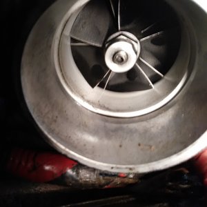
Well I got a box in the mail yesterday. Unfortunatly I have a lot going on this week so I only got a few mins to set the turbo on the engine and look at a few things and snap a few pics.

First thing I noticed is that a normal, flat plate like what most of us run for our t-4 or t4i is not going to work for this turbo.

2012-06-19_18-06-10_190.jpg


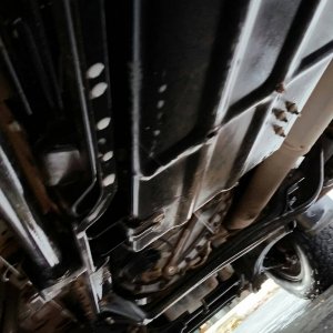
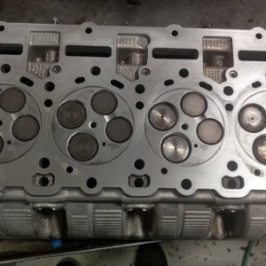
As you can see in the above picture, the 2 lower bolt holes for the up-pipes protrude lower than the bottom of the pedistal that the turbo sits on. This will require the turbo to be mounted higher by use of a bracket or spacer between the turbo and the plate. Here is another pic showing what I am talking about in case it is unclear.

2012-06-19_18-12-39_681.jpg


Second thing I noticed is the turbo is held down by 3 bolt holes. 2 of which are located on the front side of the pedistal and should not cause any issue. the 3rd is located in the back of the pedistal and as you can see below, sticks out past where the up-pipes bolt to the pedistal.

2012-06-19_18-10-19_514.jpg


This will requre the turbo to be moved forward. It is hard to see in the picture but the bolt hole is actually located directly over the oil supply and return holes in the block (when the turbo is centered in the valley and the intake is pointing straight forward)

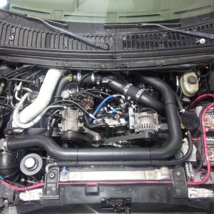
Here is a picture of the space betweeen the turbo and the intake plenums inlet with the up-pipe flange flush against the back of the mount plate.

2012-06-19_18-11-38_433.jpg


As you can see there is actually a good bit of space between the plenum inlets and the turbo inlet. With a intake y that tilts forward as it rises, I believe there would be space to have the intake attach as well. The problem arises when you remember that the turbo is sitting with the rear mounting hole hanging out over nothing when the turbo is sitting like this. In order to have that hole overtop of the plate so it can be attached, the turbo has to be slid forward approx 2".

While I didn't get any pictures of it, I did try clocking the turbo so that the intake would be more to the drivers side and the exhaust more to the passenger side. The first thing I noticed is this makes the outlet of the turbo compressor point directly towards the area that is occupied by the brake booster and master cylinder. I would have to stick the turbo under the hood before committing to this direction to see what all would be involved with connecting the hot-side intercooler pipe when the turbo is mounted in this direction.

I will be extremely busy over the next few days, and leave for vacation on friday for 10 days. I plan to use these pictures to try and map out how I want to proceed and how I plan to address the issues that I have found so far.

Here are a few pics from different angles that I took to help visualize everything. All of this are taken with the turbo sitting as it was in the first picture.

2012-06-19_18-11-28_78.jpg


2012-06-19_18-13-16_353.jpg


2012-06-19_18-13-30_585.jpg
 

Big Bore

New member
Joined
May 22, 2011
Messages
2,383
Reaction score
0
Location
9000ft in the CO Rockies
Vader, thanks for taking the time to take and post all those pics, that really helps visualize things. I've been staring at those pics for well over an hour and the best I can come up with right now is...that turbo pedestal is just every kind of wrong possible for our trucks. And since its cast as part of the housing we are stuck with it. The best I can come up with is a mounting plate that drops down into the valley and rotates the turbo which would require an interesting collector. However I don't see how else that thing is going to fit either in the truck nor mate up to the intakes and exhaust. I'm also thinking custom intakes will be needed.
 
Joined
May 18, 2011
Messages
700
Reaction score
0
Location
Austin, Tx
Just thinking out loud here, but why not lop the mounting plate off of the turbo and start over with something that is welded to the flange on the uppipes and comes down and bolts to a new mounting plate like our T4 kits use? I don't think that just because the base is cast into the housing, you have to be stuck with it, unless if you somehow end up cutting into the exhaust ports in the housing while your trying to just cut the base off. I don't have a turbo in front of me, but looking at those pics makes me think that with a little time with a flap wheel and a cut off wheel, one could have the base cut off that turbine housing.
 

Big Bore

New member
Joined
May 22, 2011
Messages
2,383
Reaction score
0
Location
9000ft in the CO Rockies
That was exactly my thought and comment way back at the beginning of this thread after seeing Jasons pics, cutting and rotating the exhaust flange and changing to something more useable at the same time.
 

bad12jr

New member
Joined
May 25, 2011
Messages
1,244
Reaction score
0
As long as it isn't cheap pot cast I don't see why it couldn't be done. A t 4 flange would be quite convenient.

Sent from my x2 somewhere
 
Joined
May 18, 2011
Messages
700
Reaction score
0
Location
Austin, Tx
That was exactly my thought and comment way back at the beginning of this thread after seeing Jasons pics, cutting and rotating the exhaust flange and changing to something more useable at the same time.

Yeah, you could do that while you were messing with it too. I don't see anything wrong with doing that, unless there is something I'm missing. Only problem would be that you'd have to know how to weld cast without cracking it or you'll have some nice drive pressure leaks. Bad12jr beat me to it.
 

Hotrodtractor

Moderator
Joined
May 18, 2011
Messages
4,934
Reaction score
14
Location
Mingo, Ohio
You guys might just be making this more difficult than it needs to be.

That turbo can be mounted a little higher, farther forward, and cocked at a slight angle. It needs raised higher so the bolt flanges clear the block, pushed forward some for clearance up above and towards the back for the up-pipes, cocked at a slight angle to make the inlet clear the intake wye (which you should remake as two 90* elbows merging together and pointing mostly forward down the length of the valley as it will give you more intake clearance).

Don't make me bust out the CAD (cardboard aided design).
 

Vader's Fury

Active member
Joined
May 18, 2011
Messages
3,302
Reaction score
1
Location
Chesapeake City, MD
I agree. I have been looking at the pics today and if I have some time tonight I am going to try a few things. Cutting the pedistal and all that is way more involved than this needs to get. Hopefully I will have some more pics tomorrow morning and some of my ideas will be a little more clear.

Anyone able to get a measurement from the base plate to the bottom of the cowl on a t-4 style setup? That will give me an idea how high the Turbo can be raised.

Edit: Moore already answered. Just for clarification you are talking about the head not the valve cover correct?
 
Last edited:

a_moore

Active member
Joined
May 22, 2011
Messages
354
Reaction score
34
Location
Blowing in the wind
I agree. I have been looking at the pics today and if I have some time tonight I am going to try a few things. Cutting the pedistal and all that is way more involved than this needs to get. Hopefully I will have some more pics tomorrow morning and some of my ideas will be a little more clear.

Anyone able to get a measurement from the base plate to the bottom of the cowl on a t-4 style setup? That will give me an idea how high the Turbo can be raised.

Edit: Moore already answered. Just for clarification you are talking about the head not the valve cover correct?

Yes, head. The oil galley portion is actually the highest point I used for refrence on my kits. iirc it is higher than the vc, or nearly the same.
 

Latest posts

Members online

No members online now.
Top