Vader's Fury
Active member
That sounds great! No rush from my end though. I dont get the turbo till early next week and I will be leaving on friday evening for a 10 day vacation in cali.
I hope to have the turbo mounted by then but that depends on if I can get all the other work I need to done by then.
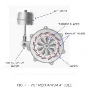
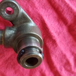
Anyone know what the connection to the turbo is called? LIke t-3, t-4 ect. I know it is not either of those but have not been able to find anything to tell me what will def fit it.
I hope to have the turbo mounted by then but that depends on if I can get all the other work I need to done by then.
Anyone know what the connection to the turbo is called? LIke t-3, t-4 ect. I know it is not either of those but have not been able to find anything to tell me what will def fit it.

")