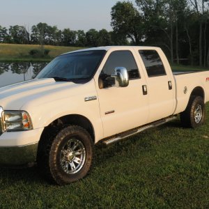
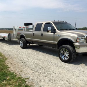
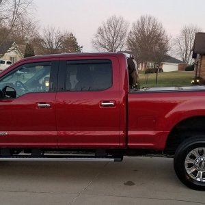
My tow pig/DD build thread. F350/Cummins 6.7/twins/6R140

me2

New member
Joined
Nov 14, 2011
Messages
548
Reaction score
0
Amazing info. What are you using to read and write can bus messages.
Thanks. A custom microcontroller board I am putting together.

Actually, there will be 3 of them. I didn't give you guys the whole story. There is more to it. But its still pretty simple.

I'm slowing working on getting some info together for a 06 CR swap into an 05 to 07 f350.
I am not sure how much CAN stuff those trucks do. It would be interesting to know.

I do know that the 2011s do even more CAN messaging than the 2008s do.

I also know that my '99 does NONE ! LOL. It does have OBDII though, so you can at least troubleshoot things. The 04.5 ECM has OBDII as well.

In the back of my mind I'm thinking that I would like to drop my 04.5CR into a 2010+ F150. If I did that, I'd update the ECM to an 06 because it supports CAN messaging. The 04.5s have some sort of a serial bus interface, not CAN.
 
Last edited:

me2

New member
Joined
Nov 14, 2011
Messages
548
Reaction score
0
Are you using the stock fuel filter? If not I'll take the connector for the fuel heater, mines missing..
The fluid connector or the electrical connector ? I have a spare electrical connector.

I'm unsure about using the stock fuel filter. I want to run dual filters on the frame, but I still want a water in fuel indication. So far it seems the only way to do that is with the stock fuel bowl. When I say dual filters, I mean a water separator filter and a 5 micron fuel filter.

FYI, I'm pretty sure that the Cummins ECM sends a CAN message when the WIF sensor goes off. I know for sure there is a WIF message that goes to the Dodge instrument panel and I assume it originates at the Cummins ECM.

Wiring things up and getting everything functioning right was always the part of the swap that I disliked the most. I will be very happy if I can handle those sorts of details in a micro controller via CAN messages.
 
Last edited:

me2

New member
Joined
Nov 14, 2011
Messages
548
Reaction score
0
Mr. ProjectV20 gave me a heads up on a couple clearance issues he is running into on his swap.

One is that the HE351VE interferes with the HVAC box.

The other is that the engine height puts it very close to the underside of the hood.

So I did some measuring.

On my truck it appears that the HVAC box is 16 inches from the center of the engine compartment. However, the HE351VE vane actuator sticks out about 17 inches from the engine centerline. The turbine portion of the HE351VE only sticks out about 15 inches.

I am now looking into whether the center portion of an HE351VE can be clocked. If it can be, one can put the actuator facing down instead of out and the problem will be solved.

Mechanically clocking it is not a problem. I'm worried about the oil drain being at 90 degress from the bottom.

I'll post what I find when I get an answer.

My 6.7 is 29 inches from the shallowest part of the oil pan, where it would go over the crossmember to the tallest part of the valve cover. But not including the EGR valve actuator which sticks above the valve cover by another 2.5 inches. Its a tall engine.

I think there is enough height between the cross member and the underside of the hood on an 08, but I can't be entirely sure as its difficult to measure with the engine still in the truck.

My twin turbo setup will stick up about 2-2.5 inches above the tallest part of the valve cover. That S475 is a big turbo !

I hope to measure an engine compartment on a truck without an engine at a local dealer later this week.
 

me2

New member
Joined
Nov 14, 2011
Messages
548
Reaction score
0
The engine stand works great. I'm very glad I built it.

I have the entire exhaust side of the engine stripped. I stopped there because I didn't have caps for the fuel system on the other side and I wanted to look into the clearance issue that Mr. ProjectV20 told me about.

I hope to finish stripping the engine tomorrow.
 

me2

New member
Joined
Nov 14, 2011
Messages
548
Reaction score
0
Posted up a question about the turbo oil drain on CompD.
http://www.competitiondiesel.com/forums/showthread.php?p=1795403#post1795403

Here is what I posted.

===============================================

Does the turbo oil drain have to face down ?

I'm swapping a Cummins 6.7 with an HE351VE into a truck and I have space issues. The VGT actuator interferes with the HVAC box.

The engine will fit no problem if I clock the center assembly down on the turbo. This will put the VGT actuator under the turbo instead of sticking out the side. However, if I do this the oil drain will move from the bottom to the side.

Is it OK to run a turbo with the oil drain going out the side versus going out the bottom ?

Thanks

==============================================
 

Hotrodtractor

Moderator
Joined
May 18, 2011
Messages
4,934
Reaction score
14
Location
Mingo, Ohio
Posted up a question about the turbo oil drain on CompD.
http://www.competitiondiesel.com/forums/showthread.php?p=1795403#post1795403

Here is what I posted.

===============================================

Does the turbo oil drain have to face down ?

I'm swapping a Cummins 6.7 with an HE351VE into a truck and I have space issues. The VGT actuator interferes with the HVAC box.

The engine will fit no problem if I clock the center assembly down on the turbo. This will put the VGT actuator under the turbo instead of sticking out the side. However, if I do this the oil drain will move from the bottom to the side.

Is it OK to run a turbo with the oil drain going out the side versus going out the bottom ?

Thanks

==============================================


You can clock the turbo some - but generally speaking the drain has to be at the bottom unless you want to pull a vacuum on the drain (not something I would want to do in a DD application).

Why don't you investigate a different manifold that puts the turbo in a different location?
 

me2

New member
Joined
Nov 14, 2011
Messages
548
Reaction score
0
Why don't you investigate a different manifold that puts the turbo in a different location?
Cost. Hassle. And unless the new manifold clocks the VGT actuator, it doesn't buy me anthing over the stock manifold. If the new manifold moves the turbo forward, then there isn't enough room to do the twins setup.

All I need to do is clock the center section and it will work.
 
Last edited:

me2

New member
Joined
Nov 14, 2011
Messages
548
Reaction score
0
Quoting someone else's quote.
==========================================
Information taken direct from the Holset service manual for the HX35/40:

Oil return pipes are permitted to decline at an overall angle of not less than 30 degrees below horizontal. All turbocharger applications require a pipe of internal diameter greater than 19 mm which has integrated connectors. To ensure oil drains into the engine under all operating conditions, the return connection into the engine sump must not be submerged and the outlet flange of the turbocharger must be 50 mm above the maximum oil level of the engine sump pan.
===========================================

I'm going to stop fretting about turbo clearance issues until I get some measurements from an 08 with the engine removed and see how ProjectV20's engine fits.

In the mean time I'll continue with the tear down and resume CAN Bus work.

For those that aren't aware, the HE351VE is a huge turbo. Thinking about it more, I am not sure if a manifold that moved it forward would work either. The reason being that its already up tight against the side of the stock 6.7 engine mount. I'll put the mount on an take a picture to illustrate what I mean.

However, I might be moving the passenger side mount forward anyway, which m ight make room.

Time to make an engine template. Stay tuned.
 
Last edited:

me2

New member
Joined
Nov 14, 2011
Messages
548
Reaction score
0
Furthermore,

==========================================
8. The orientation of the end housings may need changing in order to align correctly with all other connections. If so, ensure all fastenings are tightened to the specified torque (see accompanying data) when the correct attitude is set. In the case of Holset HC5A, HX80/82/83/85 ensure lockplate tabs are secured against the bolt heads. The orientation cannot be altered on Holset HY40V, HY50V, HE431VE, HE431V, HE531V, HE351CW and HE351V.
==========================================

http://www.holset.co.uk/mainsite/files/4_3_4-Fitting your Turbocharger.php

The center piece on the HE351VE is pinned to both the turbine and compressor sections. I guess there is a reason for that.

The turbine and compressor are not pinned to the center section on my S475.
 

me2

New member
Joined
Nov 14, 2011
Messages
548
Reaction score
0
I had my CAD department draw this up.

Cummins%25206.7%2520outline.jpg


The hatched area is the accessory drive.

Please excuse the quality.
 
Last edited:

me2

New member
Joined
Nov 14, 2011
Messages
548
Reaction score
0
I put the turbo back on the engine to get some measurements.

DSC_7094.JPG


I built a 3D model of the engine so that I can get a better feel for how it fits in a truck when I visit the Ford dealer.

It always surprises me how boxy and square these engines look in profile. I double measured everything and the model is pretty much dead on for the actual engine profile. I made it 10" wide, which is a good average for the real engine. I then marked off the areas of the major components as well as how far they stick out.

DSC_7099.jpg


I did the same thing for my last swap, but it was only a 2D model.

I'll resume tearing down the engine tonight.

I dug up my old (04.5) engine mounts. The new ones are on the left, the old ones are on the right.

Same engine bolt mounts, same mount bolt position, except the 04.5 passenger side mount is shifted about 1/2".

The new mounts have the isolator built into the mount. The 04.5s use a cartridge isolator.

DSC_7101.jpg


DSC_7102.jpg


DSC_7104.jpg


I wonder why Dodge changed the engine mount design ?

A birdie told me that 2 of the shorter mounts might work well to mount my engine.
 
Last edited:

me2

New member
Joined
Nov 14, 2011
Messages
548
Reaction score
0
Things are definitely going to be interesting height wise.

DSC_7109.jpg


The crankcase ventilation system filter and cover adds over 2 inches to the top of the valve cover.

DSC_7112.jpg


DSC_7116.jpg


If need be, A simple flat plate will cover the hole left by removing the filter assembly and cover. A new valve cover would be a prettier solution.

I totally didn't see this coming. I had lots of clearance height wise with the 5.9CR in my '99. This throws a wrench into my plan for twins as I was planning to mount the S475 so it was about 2" taller than the filter cover part of the valve cover.

I'll issue a final verdict on the situation when I put the mock engine into an engineless truck.

I really want to find the profile cutout I had for the 04.5 CR from when I put it in. Surely the 6.7 isn't that much taller than the 5.9 ?

At this point I need to thank ProjectV20 for sharing his information. I'm putting the twins mock up on hold for now.
 
Last edited:

me2

New member
Joined
Nov 14, 2011
Messages
548
Reaction score
0
I spent last night in the shop mocking up the twins setup and measuring things.

Due to the height issue, I had to totally redsign the plumbing and placement for the twins.

I bought a 2nd gen exhaust manifold and valve cover this morning. They should be here on Saturday.

The EGR cooler cracked on my 6.4 this morning. I can't drive it anymore. As soon as I get the CAN messages off it, the engine is coming out.
 

Mikeh1725

New member
Joined
Apr 3, 2012
Messages
299
Reaction score
0
Location
Grapevine, TX
I spent last night in the shop mocking up the twins setup and measuring things.

Due to the height issue, I had to totally redsign the plumbing and placement for the twins.

I bought a 2nd gen exhaust manifold and valve cover this morning. They should be here on Saturday.

The EGR cooler cracked on my 6.4 this morning. I can't drive it anymore. As soon as I get the CAN messages off it, the engine is coming out.

With the 6.4 problem it sounds like your build will be in high gear.

Great thread and looking forward to this. I miss my commonrail engine but do enjoy the upgraded Ford interior.
 

me2

New member
Joined
Nov 14, 2011
Messages
548
Reaction score
0
With the 6.4 problem it sounds like your build will be in high gear.
Yep. We missed camping last weekend and now our plans for Father's Day Weekend are in flux.

I was going to use the 6.4 to pull the trailer about 400 miles that weekend, one last trip. Not anymore.

Now I have to do a quick fix on my '99 and get it roadworthy.

BTW, I was kidding about the CAD department a few posts up. My "CAD department" is a laptop on my workbench.
 
Last edited:

907DAVE

Active member
Joined
May 21, 2011
Messages
2,166
Reaction score
0
Location
AK
I would love to have the time, funds and motivation to put this much effort into something!

Sub'd!
 

me2

New member
Joined
Nov 14, 2011
Messages
548
Reaction score
0
I had to un order my 24V valve cover. They are held on by several bolts down the center. My engine needs 6 bolts in 2 rows.

I ordered a Cummins marine aluminum cover. Part #3969481. $175. Ouch, but its blingy.

The original part number on that cover is #3969484, but it is unorderable and its just the cover. 3969481 is the complete assembly, including bolts and some breather apparatus.
 
Last edited:

me2

New member
Joined
Nov 14, 2011
Messages
548
Reaction score
0
I would love to have the time, funds and motivation to put this much effort into something!
I feel guilty every time someone makes that comment.

When its all done, I'll add up what it "cost".

Maybe this will motivate people.

20111011_001.jpg


20111005_003.jpg


The prices in the last picture are plus labour and plus core charge(s).

I do not intend to start a Ford 6.4 versus Cummins 6.7 debate war with this statement, only to point out that costs are relative. My truck will have a new engine and transmission when its done.

My budget for this swap is still $5K. I haven't added things up for a while.
 
Last edited:
Top