I started working on the turbo setup as my planned turbo setup went out the window with the clearance issue under the hood.
When I asked around, the first thing people told me was to get a 2nd gen (24V 1998 -02) manifold because it would solve the placement problem of the upper turbo. So I did.

The problem with using a 2nd gen manifold in the upright position is that the turbo housing protrude above the LOWERED valve cover by about 4 inches. Ideally, I do not want anything protruding above the lowered valve cover.

The turbo in this picture is positioned above the where it would be if mounted directly on the manifold, but one cannot mount an HE351VE directly on the manifold because the 2nd gen manifold has a T3 pattern and the HE351 has a T3i pattern or whatever they call it.
So one would have to make a non trivial adapter from one pattern to the other, which would put the turbo out further, if not up higher as well. Thus I consider the height measurement in the picture indicative of about where it would end up.
Could it be made to work ? Possibly. But not easily.
The other problems with the turbo placement using the 2nd gen manifold is that the turbo is relatively far back on the engine, putting it almost directly in front of the cowl and not leaving much room for the S475 that must fit behind it.
Wanting to have the turbo further forward had me looking for a manifold with an exhaust port forward of between the 3-4 cylinders. It turns out the stock 6.7 manifold flipped would put the turbocharger between the 2 and 3rd cylinders.
One could not mount the HE351VE on top of the inverted manifold as it would stick about 5" above the LOWERED valve cover.
One could, however, make a 180 degree mounting plate/exhaust fitting that mounts the HE351VE beside the manifold between the 2nd and 3rd cylinders.

If one does this, the turbo protrudes about 16 inches from the side of the block, which is acceptable. You wouldn't want it to go much further but it will fit in the truck, probably without removing the passenger side battery, although I will be removing the passenger side battery.
Here is a side view with a piece of cardboard to roughly simulate the dome of the exhaust elbow to be built into the mount.

Not that there is about 1.5" of space between the turbo and the manifold. This will be removed in the final mount. Right now its just sitting as close as I could get it without drilling any holes.
Here is a side view of the engine with the turbo mounted.

There is lots of room for the S475 both height wise and length wise. The S475 is a large turbo, about 10 inches from compressor inlet to exhaust outlet. It will need to be mounted high to clear the engine mounts and a bit forward so that the down pipe can clear the transmission adapter plate.
I'm using a rubber inlet elbow on the HE351 in these pictures. It could be positioned below the turbocharger or above it. It would be much tidier below, so that is where I'll strive to keep it.
The hot pipe is a piece of cake with this set up and the S475 will actually protrude less from the block than the HE351VE does.
There are a couple things that need attention to do this.
1) I have to rework the alternator mount a bit so that it is closer to the block. No big deal. A couple hours of fabricating, maybe less.
2) There isn't a lot of clearance between the very hot HE351VE turbine housing and the oil filter. Luckily this area is cooled by the fan, but I doubt that will be enough. I'll either fabricate a good heat shield or implement a remote filter setup.
I checked into the later and found this.

Its a replacement filter head. Cummins part#3284170. Its beautiful and would work perfectly. Unfortunately, Cummins wants $380 for it. I purchased a used 5.9 CR filter head and will probably modify it to implement a remote filter setup instead.
I had to remove the studs on one of the 6.7 manifold EGR ports so that it wouldn't contact the block above the filter assembly. They came out fairly easily with a stud remover.


One other thing. I was initially frowning on using the stock 6.7 manifold because people told me it was very restrictive.
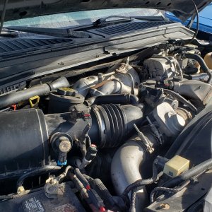
Upon direct comparison, I don't think it is restrictive at all. As a matter of fact, if the manifolds have similar wall thicknesses, the 6.7 manifold has a considerably larger cross section everywhere.
The pictures don't do the size difference justice, but in real life it is very apparent.


Today was a frustrating day in that I had lots of interuptions and the HE351VE outlet flange turned out not to fit. I should have a new flange at the end of the week and hopefully fewer interuptions tomorrow.
I received a Cummins 5.9 flexplate today. I'll be looking into the flexpate/starter/transmission adapter issue tomorrow.
Edits
Sorry for all the clutter in the background in these pictures. It makes it hard to see exactly what is going on.
In the pictures with the HE351VE mounted on the 2nd gen manifold, the center portion of the turbo would need to be rotated outward so that the center drain is on the bottom. The turbo could not be mounted like its shown in the pictures I took. I was only after the height of the turbocharger covers and did not include the VGT actuator in those numbers. The VGT actuator would stick out the side, making for a very wide installation, about 2 inches wider than using the 6.7 manifold.
When I asked around, the first thing people told me was to get a 2nd gen (24V 1998 -02) manifold because it would solve the placement problem of the upper turbo. So I did.
The problem with using a 2nd gen manifold in the upright position is that the turbo housing protrude above the LOWERED valve cover by about 4 inches. Ideally, I do not want anything protruding above the lowered valve cover.
The turbo in this picture is positioned above the where it would be if mounted directly on the manifold, but one cannot mount an HE351VE directly on the manifold because the 2nd gen manifold has a T3 pattern and the HE351 has a T3i pattern or whatever they call it.
So one would have to make a non trivial adapter from one pattern to the other, which would put the turbo out further, if not up higher as well. Thus I consider the height measurement in the picture indicative of about where it would end up.
Could it be made to work ? Possibly. But not easily.
The other problems with the turbo placement using the 2nd gen manifold is that the turbo is relatively far back on the engine, putting it almost directly in front of the cowl and not leaving much room for the S475 that must fit behind it.
Wanting to have the turbo further forward had me looking for a manifold with an exhaust port forward of between the 3-4 cylinders. It turns out the stock 6.7 manifold flipped would put the turbocharger between the 2 and 3rd cylinders.
One could not mount the HE351VE on top of the inverted manifold as it would stick about 5" above the LOWERED valve cover.
One could, however, make a 180 degree mounting plate/exhaust fitting that mounts the HE351VE beside the manifold between the 2nd and 3rd cylinders.
If one does this, the turbo protrudes about 16 inches from the side of the block, which is acceptable. You wouldn't want it to go much further but it will fit in the truck, probably without removing the passenger side battery, although I will be removing the passenger side battery.
Here is a side view with a piece of cardboard to roughly simulate the dome of the exhaust elbow to be built into the mount.
Not that there is about 1.5" of space between the turbo and the manifold. This will be removed in the final mount. Right now its just sitting as close as I could get it without drilling any holes.
Here is a side view of the engine with the turbo mounted.
There is lots of room for the S475 both height wise and length wise. The S475 is a large turbo, about 10 inches from compressor inlet to exhaust outlet. It will need to be mounted high to clear the engine mounts and a bit forward so that the down pipe can clear the transmission adapter plate.
I'm using a rubber inlet elbow on the HE351 in these pictures. It could be positioned below the turbocharger or above it. It would be much tidier below, so that is where I'll strive to keep it.
The hot pipe is a piece of cake with this set up and the S475 will actually protrude less from the block than the HE351VE does.
There are a couple things that need attention to do this.
1) I have to rework the alternator mount a bit so that it is closer to the block. No big deal. A couple hours of fabricating, maybe less.
2) There isn't a lot of clearance between the very hot HE351VE turbine housing and the oil filter. Luckily this area is cooled by the fan, but I doubt that will be enough. I'll either fabricate a good heat shield or implement a remote filter setup.
I checked into the later and found this.

Its a replacement filter head. Cummins part#3284170. Its beautiful and would work perfectly. Unfortunately, Cummins wants $380 for it. I purchased a used 5.9 CR filter head and will probably modify it to implement a remote filter setup instead.
I had to remove the studs on one of the 6.7 manifold EGR ports so that it wouldn't contact the block above the filter assembly. They came out fairly easily with a stud remover.
One other thing. I was initially frowning on using the stock 6.7 manifold because people told me it was very restrictive.
Upon direct comparison, I don't think it is restrictive at all. As a matter of fact, if the manifolds have similar wall thicknesses, the 6.7 manifold has a considerably larger cross section everywhere.
The pictures don't do the size difference justice, but in real life it is very apparent.
Today was a frustrating day in that I had lots of interuptions and the HE351VE outlet flange turned out not to fit. I should have a new flange at the end of the week and hopefully fewer interuptions tomorrow.
I received a Cummins 5.9 flexplate today. I'll be looking into the flexpate/starter/transmission adapter issue tomorrow.
Edits
Sorry for all the clutter in the background in these pictures. It makes it hard to see exactly what is going on.
In the pictures with the HE351VE mounted on the 2nd gen manifold, the center portion of the turbo would need to be rotated outward so that the center drain is on the bottom. The turbo could not be mounted like its shown in the pictures I took. I was only after the height of the turbocharger covers and did not include the VGT actuator in those numbers. The VGT actuator would stick out the side, making for a very wide installation, about 2 inches wider than using the 6.7 manifold.
Last edited:
