Rough running, codes etc...

Bushwakd

New member
Joined
May 19, 2011
Messages
177
Reaction score
0
Location
Northern,Virginia
A topside creeper and this little ratchet from http://www.harborfreight.com/1-4-quarter-inch-stubby-swivel-head-ratchet-98667.html and some ratcheting stubby wrenches makes the job easier. I have used that ratchet a many times on several injector installs and just love it. I can get it on the back valve cover bolt with just a socket and ratchet. But if you have Behemoth hands hang it up. FYI do not leave the back valve cover bolt for last.
 
Last edited:

TARM

New member
Joined
May 19, 2011
Messages
2,439
Reaction score
0
I actually have a very similar rachet. Same make and color. Dif is it is two sided. 1/4 and 3/8 I need the top side creeper. But even with that I bet you can wiggle your hand back in there and feel the head of that back bolt. For me not a chance. Close but no dice. LOL
 

davey99ps

New member
Joined
May 22, 2011
Messages
1,266
Reaction score
0
Location
Waterford WI
When mine went I thought for sure I really effed something up bad. Even got the joy of burning the living $hit out of my hands while tearing it apart in a parking lot while it was still hot. I thought i lost a rocker arm or pushrod with the noise it was making. Luckily the guys at FFD took care of me an got me back up an going. You'll be able to tell exactly which injector had the bad washer, it'll have a bunch of scale on the body. I had ffd go through mine afterwards just for peace of mind.
 

TARM

New member
Joined
May 19, 2011
Messages
2,439
Reaction score
0
It ended up being a blown tip. half of the end of the nozzle was gone. I was gonna send it back to Nate to get a new tip and throw it back in. Nate was not happy with that idea. He wanted all of the injectors back to be 100% sure none of the others could possibly have a defect as well. It seems they are made is sets and Nate was not willing to take any chances. I was trying to get away with not having to pull open the passengers side but he would not take no. So they are going back to him for a full refit.

I was really hoping it was an o-ring as that would have answered all the issues. Now with it being a nozzle I still wonder why the HPOP DC% @ idle was 14% and not the more typical 10%. So I have to wait till I get the injectors back and see if the DC% is still high like this. If so then I will have to call Gary and see if its something I need to send the stealth back and have it checked out. I have all new direct from Ford ICP and IPR so its not them. While I have the VC off I am going to replace the UVCHs and glow plugs. Already replaced the glow plug module as well. So we will see what happens.

The BTS trans should be in about the same time so I can do some full throttle runs and see what the logs look like for ICP and DC%.
 

TARM

New member
Joined
May 19, 2011
Messages
2,439
Reaction score
0
It was just the tip not the whole long nozzle. You know were the radius step is where it starts to angle down to the tip. Its a piece of that. My HOPE is it blew out the exhaust port. I was at low RPM and low throttle when it went. Not sure if that helps or not but I can hope. I hope it went into that nice bowl area and then out the valve port.
 

907DAVE

Active member
Joined
May 21, 2011
Messages
2,166
Reaction score
0
Location
AK
I'm sure your okay. I was thinking it was a larger piece.

Care to share any pictures?
 

TARM

New member
Joined
May 19, 2011
Messages
2,439
Reaction score
0
I guess I could take a bore scope and go in thru the injector port and take a look. Might have to see if I can borrow a bore scope with a smaller rod as I think mine is a tad large. Maybe if someone has a rifle scope I could borrow.

Honestly I am surprised they are not used more to check out the condition of the cylinder and pistons rather than pulling heads all the time. It would at least let you know if its worth messing with.
 

TARM

New member
Joined
May 19, 2011
Messages
2,439
Reaction score
0
Ok here ya go. I had to figure out how to setup the function on this camera to take micro close up shots as it has to bring focus way in.

Here is a shot of the tip that is in focus enough to see. This is a whole lot better than the shots I sent Nate with my phone camera LOL

Injector Broken Tip

P1050156.jpg


Injector with Good Tip

P1050163.jpg


This should give a good comparison of what was actually broken off. I did end up with one hell of a good injection rate. I was able to put 465cc in about 1 ms LOL Maybe this is a racing tip injector. LOL I did get a ton of smoke so I am sure some 16-19 yrs olds might think it cool.
 

TARM

New member
Joined
May 19, 2011
Messages
2,439
Reaction score
0
Ha Ha I do not know how you were able to do it. First the sound coming from the engine the tap tap tap of that injector was horrible/. But the smoke I am talking with almost no throttle you could not see the 4 lane hwy with big median strip behind me. LOL If that had been gasoline and someone had lit a match. OH MY!!!!!! Can anyone say FIREBALL

I am just happy to know what the issue was all this time. Its rather interesting becuase if I was not picky I would not have felt like anything was really wrong. I could just tell the idle was not quite right and it was smoking more than I know it should. But not anywhere bad enough that some of the tuning I have seen of other trucks with these size nozzles. Still it was just not right.

I actually feel luck as if that had waited another couple hours to let go I would have been that far from home on my trip with a Excursion full of people and cargo including a rear storage box in the hitch mount. No way this was going to get fixed then and I would have had a hundreds of miles to get back home to swap vehicles or have to ditch it all for a rental in that area big enough for everything for a week. So I got lucky!!!
 

Chvyrkr

Active member
Joined
May 18, 2011
Messages
2,204
Reaction score
0
Have you checked the oil to see if you ended up with fuel in the oil?

Might be a little in there, with that much nozzle gone.

It'll look like this on a paper towel/shop towel, the fuel separates from the oil.

fuelinoil.jpg
 

TARM

New member
Joined
May 19, 2011
Messages
2,439
Reaction score
0
No I did not check it yet I figured given the fuel I saw it was a given that I was gonna be changing the oil once I evacuate the cylinders of the oil and fuel that has gone in from pulling the injectors.
 

Chvyrkr

Active member
Joined
May 18, 2011
Messages
2,204
Reaction score
0
I was mostly wondering to what extent you ended up with fuel in the crankcase.
 

TARM

New member
Joined
May 19, 2011
Messages
2,439
Reaction score
0
I will check and let you know. see if I can take a pic of it/.
 

V-Ref

Active member
Joined
May 21, 2011
Messages
1,028
Reaction score
0
Location
9 miles high @ 550 mph
Sorry to hear of your troubles! Sounds like you've got in well in hand, and I know Nate will have you another eight injs better than ever. Tough times vet out the real story, and now you've got a chance to do all those little tweaks now that truck is apart.

What's the scoop on the final config of your fuel system? I know you went through some pump hell, and I remember you outlining a pretty trick fuel system before....but what's on your rig now?

I'm selfishly concerned, and want to make sure my fuel sys is pumping fuel not bubbles.
 

TARM

New member
Joined
May 19, 2011
Messages
2,439
Reaction score
0
This is a quoted post from this thread Fuel System with a Different Twist

This is the full fuel system I installed. IMO its about as good as you can get with a fuel system. The only thing I could see to really improve on this would be to use a gear or belt driven fuel pump. That would change a few things but as far as using an electric fuel pump IMO this setup addresses most everything I could think of. It removes air. Has the very best water fuel sep and awesome pre-pump filtration. With this dual pump setup each pump is only being asked to do one primary thing which is most cases is why we tend to fry pumps when used in a single pump config. It keep the hi pump cool and allow addresses any fuel sloshing issues at low tank. Fuel is brought back down to as close to ambient temp as possible which gives much better pump and injector lubrication performance as well as more BTU of energy per vol of fuel injected. It removes air and vapor. The routing causes the least formation of air or vapor. Routing into the rear inspection ports to standard 6an fitting not the sharp 90 turn of a banjo fitting. It then leaves via the smaller standard front ports. This will keep and allow the fuel pressure to remain the most consistent IMO. Final filtration is via a Donaldson 3mic that is a true 3mic 99% not nominal. Using a V10 trans cooler as the fuel cooler. Need to add a bypass loop just in case for winter time although I doubt here it will be needed. If I was way north or in AK then for sure.

The last plan for the system is to relocate it. I am relocating the batteries to the passenger frame rail. I will then move the whole fuel system to the engine bay. That is minus the lift pump as its best location is close to the tank. This will keep the system secure from curious people. Will make service easy. Will almost eliminate any possibility of damage during off-road use.


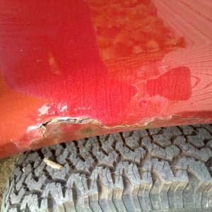
I had posted this as part of my log thread over on PSN but figured I would post it here as IMO this is going to become more of an advanced board given the membership.


After a failure of a very popular pump with a traditional setup and then one trying the all in one FASS units along with the numerous results of others with failures of Walbro pumps for various reasons I decided to start with a clean slate and work the issues from the ground up. Basically I was not happy with any of the current wheels we use so I decided to reinvent a new one.

For more complete detailed info you can reference my build thread "The Never Ending Build" if you so choose


The issues again addressed are:

  • high volume flow and high psi to support 80gph @ 75psi (800HP+)
  • head fuel rail port size
  • maximum flow thru heads and effectiveness of regulator to pressure and flow changes
  • Pump cooling and lubrication
  • Controlling fuel temp (ideal 60° F for max performance in BTU and lubricity)
  • Eliminating 1/4 tank and below sloshing issues with intake of air
  • Free-Air removal from turbulence and other causes that free entrained air
  • Maximum removal of water and absolute particles down to 2-3 microns
  • Minimize pump noise levels (stock or better)


First up will be a rough hand scribbled schematic I drew up when I was crunching all the info I had collected.


The fuel flow direction legends and hose make it look more complicated than it really is. When you break it down it only has a couple more connections than current systems and no more than a system using a Air Dog or FASS as a lift pump. Look at it for a bit and consider things like how the surge tank works and everything it actually does etc..

Look at the hose and flow routing carefully as its easy to misinterpret the flow and think there might be issues.
img633.jpg


Then here are some of the pictures I took while I was putting it all together and installing it:

The pump is a Bosch 044 they are basically a unscaled version of our SD pump model
IMG_20110720_153717.jpg


These next few are of the Surge tank. This one showing the pump and 3x-6an ORB ports
IMG_20110720_153528.jpg

IMG_20110720_153607.jpg


This one you can see a close up and see the O-ring inside to help seal the pump to the tank.
IMG_20110720_153742.jpg


These next few show the pump surge tank with its clamping ring.
IMG_20110720_153643.jpg


Jay Racing's Check valve installed on the Bosch pump's outlet.
IMG_20110720_153731.jpg


Pump and surge tank and clamp ring and hardware.
IMG_20110720_153643.jpg


Pump installed in the surge tank.
IMG_20110720_154208.jpg


A few pictures right to left of Carter 4601 pump > Dahl 150> Surge tank with Bosch 044 pump on mounting plate.
Notice I have just a few left over fittings and supplies from all the testing :doh:

IMG_20110725_220451.jpg

IMG_20110725_220346.jpg

IMG_20110725_220346.jpg


On separate mount the Baldwin 1311 filter base with Donaldson P551311 3 micron absolute single pass perf nominal should around 1 mic recommend flow rate 120 gph.
IMG_20110725_183735.jpg


V10 Trans cooler to be used as the Fuel cooler mounted in grill/bumper.
IMG_20110727_211909.jpg


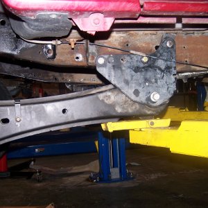
C-Channel mounted to frame rail uses 3/8" locking spring nuts to mount fuel system plate to it.
IMG_20110725_183710.jpg


The pump is a Bosch 044 pump. Its actually rated for constant pressure from 0-100 psi. There is very little effect on flow from pressure changes compared to many other pumps. But @ 70-75 psi it flows on average 80gph. It has the same internal build as our stock pumps just larger. Its about 25% larger than a Walbro. I learned a lot from speaking with a guy Kevin? at the Bosch tech dept.

The Carter 4600 series pumps have proven to be very durable and long lasting as they are a rotary vane pump so nothing to burn up. They are specifically marine and diesel rated. They are low pressure only and changes in it significantly effects the flow rates. 100 gph free flow which is how it is run in this system.

The Dahl 150 has a pressure resistance @ 80gph flow rate (its recommend flow rate) of 0.75 psi, so very small effect.


The Surge tank is tig welded alum tank. It has 3x -6an threaded ports and the pump port. The pump port is specific fit for the Bosch 044 pump it has a o-ring and works with the clamp again the ring/rim built into the Bosch pump case.

Surge tank has 1.5 liter accessible capacity for the pump (total internal capacity is closer to 3 liters. More could be accessed with the addition of a fitting to the pump inlet)
Dimensions external: 5.5"x8x"4.25"
It sets the pump so its 75% submerged
The 3 ports are -6an ORB threaded

Hoses are -10an from the 5/8 Tank pick up to the Carter. Carter is direct fit into the Dahl 150. _8an hose into the -6an port on the surge tank. -8an from the Bosch pump's check valve into the Baldwin Filter base. -6an hose to the Y . -6an hose into rear inspection port DI fittings on each head. -4an hose out the front top fuel ports exiting the heads into the regulator. -6an hose out the reg return port into the V-10 cooler. -6an hose out of cooler into the surge tank. -6an out of surge tank into old stock feed port on tank sending unit.

Each pump is wired to its own 30 amp Bosch relay that are fused protected from the feed line from the battery. Grounds go directly to battery - post and frame ground bolt. Factory fuel pump wiring harness used as control wires for the relays. All power and ground wires are 10 gauge ultra fine stranded wire.
 

Latest posts

Members online

Top